Circuit Analysis and Solenoid Working

Thread Starter

moonlystar1111

Joined Feb 1, 2024
106
Hi,

Not really, that's not the way to handle spikes. Clamping is the way it is usually done, or with a snubber circuit. You only need one transistor then and it's easier to deal with the switching of that one that way too.

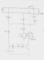
You can also check to see how fast the transistor turns off. The large capacitor takes time to discharge, but the zener and series diode could cause the transistor to turn off slowly but then sharply after that. If it turns off sharply then you need to handle the spike.

Is this a one-off circuit or are you going into production or something with this? If it's for a large production run you may want to keep costs down, but for a one-off unit (or for hobby purposes) it doesn't matter much if you add one resistor or one diode.
Okay got your point for voltage spike handling.
From the circuit the capacitor can take 250 msec to discharge. Is this slow enough? Zener voltage is almost 43 Volts.
Yeah this circuit is somewhat used for large production and thus cost optimization comes into the picture.
 

Thread Starter

moonlystar1111

Joined Feb 1, 2024
106
Hello again,

You said DPST before didn't you? But it doesn't really matter because you can make any type of simple switch.
It's good you know how to use the SPST switch already.

To make a SPDT switch you would just use two switches, but you would have one turn on at say 3v and the other turn off at 2v, something like that. So one turns on at 3v and the other turns off at 2v, or you could just invert the pulse so they both turn on at 3v (with a 5v pulse drive) but due to the inverter the second switch only turns on when the first switch turns off.
Sometimes you need a small "dead time" between the switches, which would mean it would be a break before make switch. In this case you can use two pulse sources, one set to turn on at say t=0.00 and off at t=0.99, and the other to turn on at t=1.00 and off at 1.99, and then the first one would turn back on at t=2.00, so only one switch is on at any time and there is 0.01 seconds between the on/off of the two.
To make a DPST switch (which is what you want I think) you just use two switches and set them both to turn on at 3v. Set the pulse to turn on sometime after startup.

Using these ideas you can make SPST, SPDT, DPST, DPDT, etc., even 3PDT, 4PDT, etc. To get multiple 'throws' you have to use more switches but have them turn on at different times using different pulse sources. For SP3T you'd have to use three switches but also three pulse sources. That's unless you already have logic state outputs that can drive them individually.
Yeah you're right I was looking for Dpst, it was typo mistake.
I have attached the schematic what I was trying to simulate. But I figured out that i need spdt in hot and spst in neutral.

I have shown in pink which I want to connect with diodes and solenoid, which I'm not getting exactly how it would be done.

Apart from simulation, for practical testing, can dpdt relay be used in place of this arrangement? With other side of switch connected in neutral left floating ?
How much will it affect in cost..
 

Attachments

MrAl

Joined Jun 17, 2014
13,711
Yeah you're right I was looking for Dpst, it was typo mistake.
I have attached the schematic what I was trying to simulate. But I figured out that i need spdt in hot and spst in neutral.

I have shown in pink which I want to connect with diodes and solenoid, which I'm not getting exactly how it would be done.

Apart from simulation, for practical testing, can dpdt relay be used in place of this arrangement? With other side of switch connected in neutral left floating ?
How much will it affect in cost..
Your circuit looks like it works ok (see attachment).
Yes you can use a DPDT relay just don't use all the contacts.
The cost really depends what you can find. Since DPDT relays are common you can probably find that actually cheaper.
I am not sure at all what you want to do with "diodes and solenoid".
 

MrAl

Joined Jun 17, 2014
13,711
Okay got your point for voltage spike handling.
From the circuit the capacitor can take 250 msec to discharge. Is this slow enough? Zener voltage is almost 43 Volts.
Yeah this circuit is somewhat used for large production and thus cost optimization comes into the picture.
You have to test to see that the transistor does not turn off fast. It makes no difference how slow the capacitor discharges if the zener cuts off sharply. As the cap discharges, the voltage across the zener becomes less and less, and eventually it would fall below the zener voltage causing the current to decrease suddenly, which in turn could turn the transistor off suddenly. That has to be tested.
What would worry me is if the results are not repeatable in that the transistor turns off slowly sometimes and faster other times. This has to be tested very carefully if you do not want to add a back EMF diode.
If you do add a single back EMF diode, then you have to test that the relay does not open too slowly. If the relay opens too slowly then you might have to use a zener instead of a diode.
 

Thread Starter

moonlystar1111

Joined Feb 1, 2024
106
Your circuit looks like it works ok (see attachment).

I am not sure at all what you want to do with "diodes and solenoid".
Please refer the attached circuit in this comment.

Consider the flow is--
hot line -> switch connection ->
R1->D1-> D3 -> C3, R4 & SOL

In ltspice, SW has only 2 side - one connected to power supply and other to load.
I was asking for the modification in ltspice circuit like how can i draw to get the flow I mentioned above.

I want third side of the SW that is then connected to R1 till SOL.
 

Attachments

Thread Starter

moonlystar1111

Joined Feb 1, 2024
106
You have to test to see that the transistor does not turn off fast. It makes no difference how slow the capacitor discharges if the zener cuts off sharply. As the cap discharges, the voltage across the zener becomes less and less, and eventually it would fall below the zener voltage causing the current to decrease suddenly, which in turn could turn the transistor off suddenly. That has to be tested.
What would worry me is if the results are not repeatable in that the transistor turns off slowly sometimes and faster other times. This has to be tested very carefully if you do not want to add a back EMF diode.
If you do add a single back EMF diode, then you have to test that the relay does not open too slowly. If the relay opens too slowly then you might have to use a zener instead of a diode.
Okay thanks for this.

Though not possible anytime soon, but if it is I'll try to test it in coming days and will update here.
 

MrAl

Joined Jun 17, 2014
13,711
Please refer the attached circuit in this comment.

Consider the flow is--
hot line -> switch connection ->
R1->D1-> D3 -> C3, R4 & SOL

In ltspice, SW has only 2 side - one connected to power supply and other to load.
I was asking for the modification in ltspice circuit like how can i draw to get the flow I mentioned above.

I want third side of the SW that is then connected to R1 till SOL.
Oh I think I know what you mean. You want a third contact for that one switch right?

If so, you just use one more switch but turn that switch on at the same time that you turn the other switch off, and connect two of the terminals of the two switches together to form the contact on the left. You might modify the switch itself, or just use another pulse source that is sync'd to the first pulse source but of opposite state. That creates a two phase clock pulse where one pulse is inverted from the other.
In real life that's a DPDT with one contact not used.
 

MisterBill2

Joined Jan 23, 2018
27,587
If the solenoid response time is being checked, understand that the diode will have a big effect on release times, and that the source impedance will have a big effect on operate times.
 

MrAl

Joined Jun 17, 2014
13,711
Yeah you're right I was looking for Dpst, it was typo mistake.
I have attached the schematic what I was trying to simulate. But I figured out that i need spdt in hot and spst in neutral.

I have shown in pink which I want to connect with diodes and solenoid, which I'm not getting exactly how it would be done.

Apart from simulation, for practical testing, can dpdt relay be used in place of this arrangement? With other side of switch connected in neutral left floating ?
How much will it affect in cost..
One thing I noticed about your simulation circuit is that you are switching the two switches at 60Hz. You would not be able to switch a physical relay at that speed you'd have to use a triac. Maybe you could find a solid state relay but not sure if you could switch one of those that fast either.
 

Thread Starter

moonlystar1111

Joined Feb 1, 2024
106
One thing I noticed about your simulation circuit is that you are switching the two switches at 60Hz. You would not be able to switch a physical relay at that speed you'd have to use a triac. Maybe you could find a solid state relay but not sure if you could switch one of those that fast either.
Yeah . I did that only for simulation purpose though. Its frequency will be definitely low in practical.
 

MrAl

Joined Jun 17, 2014
13,711
Yeah . I did that only for simulation purpose though. Its frequency will be definitely low in practical.
That's what I thought but wanted to mention it just in case.

It was kind of cool though because it formed a half wave synchronous rectifier, at least until it started to run out of sync. Because the timing was 8.33ms and not 8.333333333333333 eventually it would have started to produce a waveform that was partly negative and partly positive, until the polarity flipped completely and resulted in a negative half wave rectification. Eventually after that it would start the part negative and part positive again until it flipped back to a positive half wave rectification, and these cycles would continuously change back and forth over longer periods of time.
I'm not sure if there would be a way to be sure to correct that behavior for very long periods of time, using independent pulse generators for the timing instead of the wave itself. If the sim time is longer we'd have to see if 16 digits of precision would cut it. Better would be to experiment (by simulation) at a frequency of 50Hz because then the half cycle time is not a repeating decimal. Instead of 8.3333... milliseconds it would just be a nice 'round' 10ms.
 
Top