Circuit Analysis and Solenoid Working

Thread Starter

moonlystar1111

Joined Feb 1, 2024
106
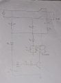
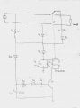
In the schematic attached I want to analyse its working. It is a part of a connecting and disconnecting mechanism. The ac input will be connected to load by changing the switch position (opposite to what is shown in the schematic).
I have few questions regarding this mechanism-
1- In the positive half cycle which side of the capacitor c1 & c2 will be positive (a or b).
2- Will this cap with R2 provides any time delay?
Time constant comes out to be around 5 sec. 5 times of it equals 25 sec, so whats happening during 25 sec? What's the purpose of 25 sec delay?
3- When c5 gets charged then only it will turn on npn transistor?
4- When c3 gets charged it will make d3 reverse bias in negative half cycle, and thus solenoid will get no power and will be disconnected?
5- So is it not a continuous duty solenoid?
6- Also, if im wrong in analysisng, how is it overall working here..
 

Thread Starter

moonlystar1111

Joined Feb 1, 2024
106
The circuit is incomplete. V1 is a floating isolated supply, the transistor cannot conduct, the relay will not operate.
Consider the negat
1) How do you get that value? The time constant of C1/C2/R2 is 50 milliseconds.
2) Are the diodes really 1N4148? They have a reverse voltage rating of only 100V.
1)Oh calculation mistake. Right it would be 50 milliseconds.
2)No all are not in4148. Except D4, all are in41007 and its reverse voltage is 1000v. I wrote 4148 that just for idea here.
 

Alec_t

Joined Sep 17, 2013
15,119
Please consider V1 to be grounded at neutral side.
But you haven't identified the neutral side. If we assume it's the '-' node of V1 then, depending on the zener/breakdown voltage of D6, there is probably enough current passing from V1 via D5, D6, D4 to destroy Q1.
 

Thread Starter

moonlystar1111

Joined Feb 1, 2024
106
But you haven't identified the neutral side. If we assume it's the '-' node of V1 then, depending on the zener/breakdown voltage of D6, there is probably enough current passing from V1 via D5, D6, D4 to destroy Q1.
Zener voltage is 43V. Npn is MMBTA42.
 

Alec_t

Joined Sep 17, 2013
15,119
So peak current through Q1 base-emitter junction wiil be (120-43-3*0.65)V/47R = 75V/47R = 1.6A and the average dissipation will be ~ 310mW. I can't see Q1, D4 or D6 surviving.
What are the voltage and current ratings of the solenoid/contactor coil?
 

Thread Starter

moonlystar1111

Joined Feb 1, 2024
106
1) I suppose 1.6A is the peak current through R3, not directly the base-emitter current through Q1. The actual base current would be much lower due to the presence of R4 (100k) in the base circuit. Around 0.423 mA is closer to the actual base current considering the resistances directly in the base-emitter path.
Is this analysis correct?

2) For solenoid, Nominal current handling capacity would be 20 A or higher. And voltage would be 120 V dc. Its coil resistance is 3k ohm
 

Alec_t

Joined Sep 17, 2013
15,119
C5 will charge up to ~45V.
Are you sure R3 is only 47 Ohms and not 47k Ohms?
Where did you get the circuit from? It doesn't look right to me.
 
Last edited:

Thread Starter

moonlystar1111

Joined Feb 1, 2024
106
C5 will charge up to ~45V.
Are you sure R3 is only 47 Ohms and not 47k Ohms?
Where did you get the circuit from? It doesn't look right to me.
Sorry for the late reply as I was analysing the circuit again. There is correction in the circuit. A resistor, say R5 of 22k will be placed before zener D6 and after polar capacitor C5. Along with it, R1 is 47 and R3 is 100.

I want to know the flow and working of circuit which I have provided. It is a complex circuit and I picked a part to solve it.
 

Alec_t

Joined Sep 17, 2013
15,119
It would help others to help you if you posted a corrected circuit, showing actual diode types and new component values and placements.
What exactly is the circuit supposed to do, and with what timing, in the way of controlling the relay/solenoid?
 

MrAl

Joined Jun 17, 2014
13,707
Did anyone mention this yet?

The transistor has no protection from the back emf of the coil. Usually the minimum is a reverse connected diode even though that is not the best. Without that the transistor could get stressed way too much.
 

Thread Starter

moonlystar1111

Joined Feb 1, 2024
106
It would help others to help you if you posted a corrected circuit, showing actual diode types and new component values and placements.
What exactly is the circuit supposed to do, and with what timing, in the way of controlling the relay/solenoid?
D1 D2 D3 D5 - IN4007, D4 -IN4148
Q1- MMBTA42
D6 - Zener voltage 43V
Input - Sin 120v 60Hz

When power is given, the switch will change its position to connect the load with the help of solenoid.
 

Attachments

Thread Starter

moonlystar1111

Joined Feb 1, 2024
106
Did anyone mention this yet?

The transistor has no protection from the back emf of the coil. Usually the minimum is a reverse connected diode even though that is not the best. Without that the transistor could get stressed way too much.
Yeah you have got a point. I will look over this
 

Thread Starter

moonlystar1111

Joined Feb 1, 2024
106

Attachments

MrAl

Joined Jun 17, 2014
13,707
I see no circuit attached.
Unfortunately that leaves me unable to provide any useful comments.
Hi,

Here's a cleaned up version for somewhat easier viewing.

[A little off topic but may help future diagram postings]
What is a little interesting is that if the original diagram as is with no cleanup was recompressed at a Jpg quality setting of 20 the file size goes from almost 800k down to around 100k, a factor of 8 to 1, with no noticeable artifacts.
 

Attachments

Last edited:
Top