Facebook
 Google
 GitHub
 Linkedin
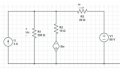
]also i do not seem to understand what happens in the single line that connects the two circuits .

Last edited by a moderator:
| Thread starter | Similar threads | Forum | Replies | Date |
|---|---|---|---|---|
|
|
Circuit Analysis problem eluding me... | Homework Help | 18 | |
|
|
Circuit Analysis Problem | Homework Help | 6 | |
|
|
AC circuit analysis problem | Homework Help | 11 | |
|
|
Problem about Summing Amplifier on LTSPICE | General Electronics Chat | 9 | |
|
|
I'm stuck at couple points in the problem | Homework Help | 45 |