Yes, exactly — if the connector or wire is damaged, a clean solder joint to the board should fix it. Just make sure the area is completely dry and use heat-shrink tubing or waterproof sealant to protect it afterward.
Am assuming those wires have not been disturbed. However, that's a good question. If someone did rewire it - there's the chance it COULD be wired backwards. I'm wondering if there's a way for the TS to make sure power from the PS is on the correct side of the controller/driver board.
I ran a voltage tester on the two outputs as requested earlier and got current.
if the resolder job is the proposed way forward, how simple is that as a job for a total newbie to this, or am I best getting someone who may work with computer chipsets to do it for me ?
Am assuming those wires have not been disturbed. However, that's a good question. If someone did rewire it - there's the chance it COULD be wired backwards. I'm wondering if there's a way for the TS to make sure power from the PS is on the correct side of the controller/driver board.
LED's are not only current based devices they are also polarized. They have a positive side and a negative side. Wire them backwards and they won't light. Force too much current through them backwards and they'll blow out.
What I would do on my work bench if I had this job to do is mark which wires are connected where, then carefully remove the output wires first. Then power the unit and test for proper voltage on the output side. If it seems to be working properly I'd get another LED and hook it up to determine which wire is positive even though it claims on the board which is V+. Knowing the controller is working I'd then touch the wires first the way they came off. I would expect the lights to work. But if not I'd then try swapping the two wires. If the lights light up then the whole problem would be that it was wired backwards. If it still doesn't light up I'd look for the first common point where all the LED's connect back to. With that tangle of spaghetti that might not be so easy to do. But as sghioto said, it could be an open line somewhere. The next test would be to find it.
Years ago the way things were wired if one bulb went out the whole string would go out. You'd have to find the dead spot and replace the dead bulb. Today they make them so that if one bulb goes out the rest of the string continues to light up. So I don't think you have a bad LED in the string(s) but rather, if it is a simple open circuit then it would probably be a spliced junction. However, you DID mention that water got into the controller and that's when problems began.
On that premises, if water got in it's understandable that it wouldn't work. But once dry it should work. The way those solder joints look - I'm heavily leaning to saying either the solder joints are bad or as sghioto suggested, it could be wired wrong IF (big IF there) but IF someone rewired it there's a chance it was wired incorrectly. Unfortunately this is not on my bench so I can't test it for you. It's up to you to figure it out. This is about all I can give you.
I was just re-reading post #13 when suddenly I remembered working on a 24VAC sprinkler system. Even though there was power at the sprinkler valve, the valve wasn't opening. So I bought a new valve only to have the exact same thing continuing to be the problem. I began to fear that it was a plumbing issue. But I decided to swap control lines. Suddenly the valve that wasn't opening was now functional and the donor valve wouldn't. So I traced back the wiring to several splices in the sprinkler control lines that were buried under ground and protected with just black tape. Moisture had gotten in and contaminated the connections to where they would pass voltage but not sufficient current to open the valve.
What does that have to do with your issue? It's that corrosion in the connections. You could be reading voltage but it can be so bad that enough current can't get through and light the lights.
DO YOU HAVE soldering tools and solder? If so then you really need to clean up those connections. I strongly suspect the issue may be fixed right there. But even that's not a guarantee. It can be incorrectly wired just as sghioto said.
"Bent some of the wiring" means a chance a wire is broken somewhere but not separated. I've seen damaged wires broken inside the insulation so you can't SEE the damage but it's there.
"Had professional strip wiring" tells me someone messed with the wiring. Who was the professional who stripped one or more wires? Can you be sure they put them back correctly?
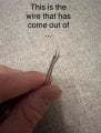
[edit] on top of all that - it looks like the wires may be aluminum wires. Aluminum wires can be brittle and easily broken.
I really don't like the product you bought. Made in China means it's likely to be made of Chinesium. Garbage in other words. You may be chasing a failure you can never catch up to.
You said you had some one re wire this the wires on those leds have plugs that you can only plug in positive positive negative the negative but were you soldered them? They could’ve reversed them
OK, a whole lot of comments. FIRST, though, those lights change colors??? With only two wires?? THAT means that there is a lot more than just DC on those wires.
LOOK VERY CLOSELY, and you will see that one side of the wire has a tiny rib molded on, the other side does not. OR it might be a tiny stripe on only one side, I have seen both methods recently. Which is positive is unknown. BUT if it is wrong, it will not work right.
The secret of re-soldering connections correctly is to only take one at a time apart!! BUT while the four solder connections were not pretty at all, they looked solid enough to me. A poor connection will come apart. CERTAINLY there is no transformer in that controller, probably not in the power supply either. It would be a switcher because they are cheaper to do currently.
Hi Tony, forgive me / that is unrelated and from a different product that shouldn’t have been in shot.
Although a total newbie, I am willing to give a resolder a go - and can purchase some very affordable kits to try this before throwing too much at an issue that may be unresolvable.
If I understand the comments correctly, are the leading suggestions that it may be a faulty connection on the driver / or an open circuit (if the latter how can I check and test for this)?
OK, a whole lot of comments. FIRST, though, those lights change colors??? With only two wires?? THAT means that there is a lot more than just DC on those wires.
LOOK VERY CLOSELY, and you will see that one side of the wire has a tiny rib molded on, the other side does not. OR it might be a tiny stripe on only one side, I have seen both methods recently. Which is positive is unknown. BUT if it is wrong, it will not work right.
The secret of re-soldering connections correctly is to only take one at a time apart!! BUT while the four solder connections were not pretty at all, they looked solid enough to me. A poor connection will come apart. CERTAINLY there is no transformer in that controller, probably not in the power supply either. It would be a switcher because they are cheaper to do currently.
Back in post #18 we see a picture of a 24 volt DC power supply. What I suspect now is that a splice has been made with the connections reversed. THAT is what I would first suspect from somebody who was unable or unwilling to observe and follow the polarity markings. Certainly the broken end that we are shown indicates that the wire broke under tension. So there may also be a conductor pulled out of a connector along that same section. A close inspection, with adequate light and a magnifier is the next step.
 Facebook
 Google
 GitHub
 Linkedin