Changing LED transformer board

Tonyr1084

Joined Sep 24, 2015
9,744
If I understand the comments correctly, are the leading suggestions that it may be a faulty connection on the driver / or an open circuit (if the latter how can I check and test for this)?
Here's my opinion on this matter:
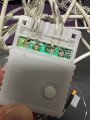
1) Possibly mis-wired. You DID say you had a "Professional" do some work on it. For my money the "Professional" was anything BUT a "Pro". What makes me come to this opinion is the solder job. If he were truly a pro he would have never left solder joints looking like that. So my #1 choice is it's mis-wired.
2) Could be a bad solder joint. Again, it's the way solder looks. I've looked at solder joints by the hundreds of thousands per year. I know a good joint when I see one; and I know a bad one just as quickly. I once had an interview which included looking at a mother board. I was told they knew where every reject was on the board. My job in the interview was to find them. I looked at that board three times over but couldn't find anything I would have rejected. When my interviewer came to see how I was doing and I told him "I've looked at this board three times and can't find any rejects." I got the job on the spot. He told me that every interviewee before me found things they would reject for. The point of the test was to see if I truly knew the standards by which nearly all electronic assembly is held to. So I know solder.
3) Possible open circuit somewhere. One way to test for this is to flex the wire everywhere possible. If you have only one broken wire when you flex it you'll see the string of lights light up. If not - then there's just two possibilities; A) dead controller. B) possible multiple breaks in the wiring. Multiple meaning two or more.

The only way to see if you have ANY broken wires is to test continuity from end to end. You should get less than 5 ohms. If you get a low resistance then you have a good wire. If it's broken anywhere, even in multiple places you'll never get continuity. And I'm not talking about checking for continuity from the + to the -. You'll be reading through all the components. However, if you DO test that way and the wiring is not the issue then you'll get a high resistance. Hundreds of ohms to a few thousand ohms. But if you get "OL" then it's likely an open circuit.

Quick overview of what people call an electrical issue: Some call it a "Short", others may call the same issue "Open". A circuit is a circle. There is continuous flow all the way around the circuit. If you break the circle (or circuit) you don't get any flow at all. A short is like a smaller circle inside the bigger circle. In other words it's a shortcut from starting point to the ending point. If you need me to draw a picture just ask.
 

MisterBill2

Joined Jan 23, 2018
27,524
Consider once again that in this system POLARITY MATTERS!! and so it is very important to verify that the polarity thru the splice/repair, is correct.
NEXT, consider that thin wires in a stretchable plastic jacket can break, once again, it is time to inspect, at least the areas that were subject to stretching but did not break completely.
A simple continuity test, done with the power off, can show the presence or absence of continuity.
 

Thread Starter

Tgi8

Joined Oct 3, 2025
21
I will be testing the circuit tomorrow for any breaks / continuity etc.

I had a thought that has only now just occurred to me, the split / repaired wire occurred in an extension part of the LED’s (the device is split into three and connected with a 2 pin standard LED connector - you know the ones, can sen photo if needed) - which is currently unconnected.

with this in mind, I’m able to look at a much smaller set of wiring, but could also point to a dead control unit ?

I have taken great interest in all the points about polarity, in that even with the repaired wire not currently part of the set up, could that initial ‘repair’ work have tripped the rest of the polarity?
 

MisterBill2

Joined Jan 23, 2018
27,524
CERTAINLY getting the polarity reversed would cause problems. AND certainly the polarity identification on the wires may be a challenge to see. AND broken conductors are always a possible problem. Water damage inside that plastic housing might also be a cause of failure. So there are quite a few things that might be the problem. AND, if that suspected poor solder joint is guilty, it should fall apart with just a slight wiggle. BUT I doubt that is the point of failure.
 

Thread Starter

Tgi8

Joined Oct 3, 2025
21
An update on this…!

I took the product to a local IT repair business that works with soldering motherboards for them, to ask if they could desolder and resolder the connections to the LED driver.

That didn’t work but when he connected them to a DC supply we were able to get the device light up (all in white - so now looking to source a new RGB LED driver), to install on to see if we can return full functionality!
 

MisterBill2

Joined Jan 23, 2018
27,524
Since you have verified the connections are OK, now you can very carefully open that controller and see if draining the waterout will fix it. Nothing to lose at this point.
 

Thread Starter

Tgi8

Joined Oct 3, 2025
21
Since you have verified the connections are OK, now you can very carefully open that controller and see if draining the waterout will fix it. Nothing to lose at this point.
We have been able to make the colours change by pulsing the power into the wires, we have opened up the LED RGB controller and believe it is faulty. We have not been able to find a matching controller so it's probably non-standard. The IT specialist is reviewing if the current controller is fixable.

To confirm, if we source a replacement, from the photos shared previously, can anyone advise specifically what we are looking for?

24v / 2A RGB connector ??
 

MisterBill2

Joined Jan 23, 2018
27,524
OK, the first photo provides the name of the company and the model number of the controller. The bad news is that probably the shipping charge for a replacement controller will cost more than a replacement for the whole system at a current local store.

BUT, given that you have been able to duplicate some control, as mentioned in post #48, it should be possible to develop a replacement controller using a series mosfet and some sort of OFF/ON pulsing instructions, and some external logic, possibly a small processor module.
And if you succeed in cracking the code, you could share that on this site.
 

Tonyr1084

Joined Sep 24, 2015
9,744
What I'd like to see is the controller uncovered. It could be a simple fix. It could be more involved. It could be uneconomical to fix. We've already seen those other pictures. Please pop the cover and show us the guts. If you can completely remove the board then show us both sides of the guts. If the plan is to disconnect all the wires then mark each wire with a black marker. Single dot for the left most wire, two dots for the next, 3 for the third and 4 dots for the last wire. You could leave it blank but then it could cause confusion.
 

Tonyr1084

Joined Sep 24, 2015
9,744
View attachment 356921
image of exposed circuit board as requested.
Requested BOTH sides. And that board needs to be cleaned up. Isopropyl alcohol and an old toothbrush should clean it up. Don't scrub too hard, just clean it up. And show both sides of the board please.

Contamination can be an electrical pathway between circuits that are not intended to be connected. In other words, shorted. That's why it's important to show us both sides.
 

Tonyr1084

Joined Sep 24, 2015
9,744
There is some obvious water damage at the bottom of that image. Quite possibly repairable.
Actually that whole board looks like it was hand soldered by a 9 year old. Given it comes from China - that's not so hard to believe. As for damage - it's hard to tell with such a dirty board. Would love to see that board cleaned up. Then we can make some sort of sense from just looking at it.

[edit] That solder job wouldn't even pass for a Class II product. It meets Class I, but I'm accustomed to looking at Class III products. Military, Aerospace, Medical, Automotive. What am I forgetting? BTW: Class I is children's toys and other garbage. It was warranted for one year. You got your one year out of it. {end edit}
 
Last edited:

activerfid

Joined May 30, 2020
31
Lost track a little on this one, but as suggested the PCB looks to need a proper clean with IPA. There seems to be track damage next to R1 and one end of R1 (5.1k Ohm) may be damaged. There are some areas which look like components have been removed. I would take a few steps back to determine if all the LEDs were working after all the wiring fixes were made and they faded out or stopped working afterwards. That would sort of imply the wiring was correct and it's just the state of the PCB that is the issue. I do hope you noted which wire was where prior to photographing the PCB.
 
Top