Facebook
 Google
 GitHub
 Linkedin
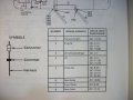
SureYes. That shows that the signal from the doors changes:
1. from "open" to "Ground" when ANY door is opened
2. from "Ground" to "open" when ALL doors are closed
So...the door signal should connect to the -Door Trigger input on the alarm module.
The -Door Trigger is the "Green" wire on the Alarm module wiring harness.
Test for -Trigger:
When any door is open:
The -Trigger should change from Open to Ground.
Connect the +meter lead to +12v and connect the -meter lead to the -Trigger on the alarm module.
When all the doors are closed, the meter reading should be "floating".
When any door is open, the meter reading should be "+12".
Meanwhile...
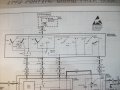
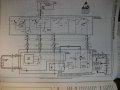
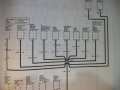
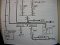
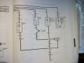
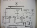
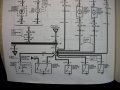
Can you post the portion of the schematic that shows the rest of the door wiring? I want to see what else the door switches are connect to...
Attachments
-
 2.6 MB Views: 2
 -
 2.6 MB Views: 2
 -
 2.6 MB Views: 2
 -
 2.6 MB Views: 2
 -
 2.6 MB Views: 2
 -
 2.6 MB Views: 2
 -
 2.5 MB Views: 2