Curious on how to activate a cymbal monkey through the alarm circuit on a digital alarm clock. Wiring schematic is much appreciated. Thanks in advance!
You would need to know how your alarm clock alarm is triggered. Then from there you'd build a latching circuit that would be activated by that alarm trigger. That could trigger a relay that activates a power supply or battery that powers the monkey. But to ask for a schematic without knowing how your alarm triggers - you're not going to find an answer. There's a lot of work you need to do before we can begin to help you.
It also depends on how much you know about electronics and electrical wiring.
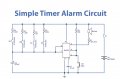
Thanks for the info. I found a simplified schematic of a battery powered alarm clock. Prolly gonna tear one of these apart to find similarities hopefully. I was thinking of tapping into the signaling trigger circuit to the buzzer/ removing the buzzer and replacing it with a low power relay coil side. Also on the monkey side removing the power switch and installing the other side of the relay. The monkey is already powered by 2 1.5v D cells.
Currently putting together a parts list of a cheap ass battery powered alarm clock, mua monkey, and a small low powered relay. I believe I can replace the buzzer with the relay coil side and replace the monkey on off switch with the other side of the relay
Currently putting together a parts list of a cheap ass battery powered alarm clock, mua monkey, and a small low powered relay. I believe I can replace the buzzer with the relay coil side and replace the monkey on off switch with the other side of the relay
Curious on how to activate a cymbal monkey through the alarm circuit on a digital alarm clock. Wiring schematic is much appreciated. Thanks in advance!
I don’t think I would need a full schematic of the alarm clock. Just the signaling circuit to the buzzer. That way I can remove the buzzer, add a low trigger relay and feed the monkey.
Assuming you take the signal from the buzzer on the alarm clock, which the above is not an alarm clock it's a timer, and since an alarm clock beeps on and off repeatedly until I'm annoyed enough to get out of bed and shut it off (I never put the alarm clock next to the bed) your monkey would run intermittently along with the beep - beep - beep of the clock's alarm.
What voltage is the alarm clock putting out? is it a pulsed beep? How much current can it support? Do you want the money to activate and remain activated until you shut the alarm off? If you latch the monkey ON you will not only need to shut off the alarm but also deactivate the latched relay.
If you go with a transistor as the switch you'll need a lot more circuitry to latch it on. Otherwise your monkey will be psychotic and not know if it wants to be ON or OFF.
View attachment 351037
Assuming you take the signal from the buzzer on the alarm clock, which the above is not an alarm clock it's a timer, and since an alarm clock beeps on and off repeatedly until I'm annoyed enough to get out of bed and shut it off (I never put the alarm clock next to the bed) your monkey would run intermittently along with the beep - beep - beep of the clock's alarm.
What voltage is the alarm clock putting out? is it a pulsed beep? How much current can it support? Do you want the money to activate and remain activated until you shut the alarm off? If you latch the monkey ON you will not only need to shut off the alarm but also deactivate the latched relay.
If you go with a transistor as the switch you'll need a lot more circuitry to latch it on. Otherwise your monkey will be psychotic and not know if it wants to be ON or OFF.
The monkey is two D cells 1.5v each. The alarm clock I’m considering is a bell type (ringer) and it is also battery powered with a single AA. Wouldn’t the relay reopen after you stop the signal on the alarm clock? Curious because it would be a N/O relay
The alarm clock I’m considering is a bell type (ringer) and it is also battery powered with a single AA. Wouldn’t the relay reopen after you stop the signal on the alarm clock?
So it's a constant ringing of the bell? If so, and it's powered from a single battery (1.5V new) you can use a transistor as a switch for the monkey. You can also use a MOSFET but either way you'll need a few additional parts. The guys here are pretty sharp with FETs and Transistors. Let's see what they say.
 Facebook
 Google
 GitHub
 Linkedin