Facebook
 Google
 GitHub
 Linkedin
geekoftheweek
- Joined Oct 6, 2013
- 1,429
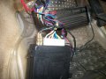
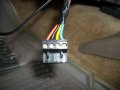
It looks like C211 goes to the wiper motor. If I'm looking at the diagram right it goes through the firewall, through another grommet, then back through the firewall again. Although it doesn't show anything I would bet there is a ground block on the engine side of the firewall where the harness goes through. Other than that I'm at a loss without actually seeing the car and the rest of the diagrams. If nothing else take a piece of the same size wire and splice in somewhere close to C211 and run it to a grounding point.The pictures shows the wiper switch, radio ,cigar lighter etc. is connected to C211 ground. For all I know the EQ could have failed due to ground issue. I am going to connect the EQ to a battery and see if it works. It did cut off once in a great while. Thanks