Facebook
 Google
 GitHub
 Linkedin

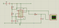
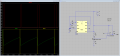
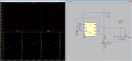
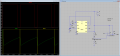
Well the comparator idea is much simpler. You use a rectangular wave generator (similar to a square wave) to charge a capacitor, then quickly discharge it. That gives you a kind of curvy ramp.Is my new idea the comparator idea that you had, i chose my switching frequency to be 100kHz
The curvy ramp goes to one input of the comparator, the other input gets the voltage reference for setting the pulse width. The output of the comparator is a PWM signal that varies almost linearly with a change in reference input.
The wave generator is also a comparator set up as a simple oscillator that generates a pulse width that has almost the same time period as the time period of the frequency you want to use. So say the period you are using is 10ms, then the pulse width would be maybe 9.9ms or something like that. During the 9.9ms the cap is charging, and during that remaining 0.1ms the cap is discharged. Then the cycle repeats.
This was used in a professional design I was working a long time ago back in the early 1980's. It was very stable even when feedback was added.
I also used this idea for a PWM for use with a triac controller to control a 15 amp AC motor. There was no feedback in that design however.
I might be able to draw the circuit at some point, but you should think about this first anyway and see what YOU can come up with given this new information. Part of learning involves thinking for yourself, sometimes very deeply. It can also be very rewarding when you come up with something that actually works well.