Circuit Building Homework help

Thread Starter

SaraB2026

Joined Apr 19, 2026
2
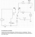
Hi! I am a student in an electrical class for my Doctorate. However, I do not have previous electrical experience (this is a one off class they said I needed). I am having trouble putting the circuit onto a breadboard. I just cannot picture at all how the schematic is supposed to translate to real life. I don’t really understand the how to use the socket or the relay. Any help is welcome! I will attach a photo of the schematic as well. Thank you!
My components needed (which I have) are:

  • Battery cap
  • Socket for relay
  • 3300 capacitor
  • Red LED
  • Toggle switches (x2)
  • Diode
  • 1KQ resistor
  • Jumper wires
  • 9V Battery
  • Relay
  • Lamp
  • Yellow LED
 

Attachments

WBahn

Joined Mar 31, 2012
32,746
What is your doctorate in?

What is the purpose of this class?

What is the purpose of this assignment?

That will help give some context behind this assignment.

I'm assuming, largely by process of elimination, that the circle with the X in it represents the lamp.

I'm guessing (and that's all it is) that this assignment has very little to do with the circuit, but that the circuit just provides the example for a task that is really unrelated to circuits, such as the ability to take a diagramatic representation of a physic object and realize that object. In other words, the assignment could have been a picture and a bunch of Lego block or a 3-view drawing and some erector set parts.
 

dl324

Joined Mar 30, 2015
18,260
Welcome to AAC!

As this is schoolwork, you need to show some effort before members can offer any guidance.
I just cannot picture at all how the schematic is supposed to translate to real life.
There's a 1:1 correspondence between nodes on the schematic and nodes on the breadboard.
I don’t really understand the how to use the socket or the relay.
A part number, or picture, of the relay would be helpful.
I will attach a photo of the schematic as well.
That's a poorly drawn schematic. Maybe that was the point to see if you can figure out how to translate from a poorly drawn schematic to breadboard.
 

Thread Starter

SaraB2026

Joined Apr 19, 2026
2
My Doctorate is in Forensic Science with an emphasis on Forensic Arson and Explosives. This class is Identification of Destructive Device Fuzing Systems. The purpose of this assignment is to build the circuit from the schematic (I did not draw it, this was provided by the professor) and then write a report on what I would change in efforts to make this an IED system.
 

MrChips

Joined Oct 2, 2009
34,690
Tell your professor that members from All About Circuits have examined the circuit and have determined that the circuit as drawn is flawed. The capacitor never receives a charge and LED2 will never light up.

Another error is, if the DC resistance of the relay coil is low, lower than 100Ω, LED1 will likely blow when S1 is closed.
 

joeyd999

Joined Jun 6, 2011
6,242
Tell your professor that members from All About Circuits have examined the circuit and have determined that the circuit as drawn is flawed. The capacitor never receives a charge and LED2 will never light up.
At least tell him why: there is no ground connection to the battery.
 

WBahn

Joined Mar 31, 2012
32,746
Tell your professor that members from All About Circuits have examined the circuit and have determined that the circuit as drawn is flawed. The capacitor never receives a charge and LED2 will never light up.
We already know, give the details of the purpose of the assignment, that the circuit, as given, will not do what it is purportedly supposed to do (act as the fusing element, in some way, for an IED). Presumably it is in the ballpark. Also, presumable, the TS has been told what behavior the circuit has to have in order to work as that fusing element? Is the lamp the fuse? What determines that the IED has been set off? Without knowing that, it's impossible to know what changes can make the circuit "work".

As for building the circuit from the schematic, draw a box around each separate component that matches what you have been given. A couple of them (battery connector and relay socket) are only implied by the schematic.

For instance:

1776629722533.png

All the schematic is showing is which connects are made between the various components -- that is what the breadboard (which holds the components) and jumper wires (which are used to make the connections) are for.

Note that the "ground" symbols (the green boxes) are merely a shorthand convention to reduce the clutter in a schematic. All of the ground symbols simply connect to the same node.

As noted previously, the circuit won't do much of anything, other than close the relay, as drawn. The issue there is related to a missing ground connection (a common mistake circuit designers, or your IED designer, make).
 

boostbuck

Joined Oct 5, 2017
1,037
It does seem a shame to base the exercise on a nonsense circuit. It wouldn't take much effort to use a circuit that gave a bit of positive feedback to the constructor as a reward for getting it right.
 

Pyrex

Joined Feb 16, 2022
501
My Doctorate is in Forensic Science with an emphasis on Forensic Arson and Explosives. This class is Identification of Destructive Device Fuzing Systems. The purpose of this assignment is to build the circuit from the schematic (I did not draw it, this was provided by the professor) and then write a report on what I would change in efforts to make this an IED system.
As you said, this diagram was drawn by the professor. It seems that this professor likes jokes. Maybe he drew such a diagram on purpose to make fun of the student??
 

panic mode

Joined Oct 10, 2011
4,913
seriously guys, do you even hear yourselves...?

this position is NOT for someone to flip burgers, deliver pizzas, cut grass or greet walmart shoppers.

so WHY is the circuit supposed to be perfect? don't you think this may be BY DESIGN?

i would imagine that some percentage or people interested in mayhem like arson and improvised bombs are not exactly the experts. in case you missed that, the position is not to hire those loony tunes... quite the opposite.

when someone is HIRED to be a FORENSIC EXAMINER, that person better be a god damn EXPERT. who the hell wants to hire a DOCTOR that can't do his/her job? person that claims superior knowledge but knows LESS than any bomb technician on the planet - for a well paid office job that has no skin in the game? i would EXPECT ... no.. i would DEMAND that doctor is more than capable of RECOGNIZING actual INTENT of the circuit, and then write report on that, INCLUDING how to FIX any flaws that circuit may have.
so dear doctor, if you want that job, you better get the breadboard and start learning how to wire circuits. there is a circuit in almost every explosive device out there. face the challenge and deal with it... stop hoping that someone else will carry your duties for you. this class is literally called "Identification of Destructive Device Fuzing Systems".
so buckle up... aren't women able to do same job that man can?
 
Last edited:

Pyrex

Joined Feb 16, 2022
501
Let SaraB2026 explain what the function of this device is, and the forum participants will try to draw a diagram.The essential thing is that it is necessary to clearly explain what function this device is supposed to perform
 

dl324

Joined Mar 30, 2015
18,260
Let @SaraB2026 explain what the function of this device is, and the forum participants will try to draw a diagram.The essential thing is that it is necessary to clearly explain what function this device is supposed to perform
She already did that in post #4.
The purpose of this assignment is to build the circuit from the schematic (I did not draw it, this was provided by the professor) and then write a report on what I would change in efforts to make this an IED system.
Apparently, the circuit doesn't work and she's supposed to document what she'd change to make it work.
 

Alec_t

Joined Sep 17, 2013
15,112
So the end result should be a circuit that does work. If that circuit, or the right way to build it, gets published here it would act as good training material for some bad actor intent on building some nasty device!
 

WBahn

Joined Mar 31, 2012
32,746
So the end result should be a circuit that does work. If that circuit, or the right way to build it, gets published here it would act as good training material for some bad actor intent on building some nasty device!
Not much of a risk of letting the secret out of the bag, there.

The thing we need to keep in mind is that this is an assignment aimed at letting the student exercise and develop THEIR skills at looking at a circuit and examining it and identifying its deficiencies and how to fix them. That goal is greatly compromised if anyone spoon feeds solutions to them. Let them do what they are expected to do and propose their solutions or at least their thoughts. Then we can help by pointing out things they are missing or need to consider, preferably in a way that nudges them in the right direction without shining a big spotlight on it so that they can still learn from the experience of struggling to see as much as possible on their own.
 

gray-b

Joined Aug 4, 2025
87
Surely the circuit is drawn upside down. Normal method is to have + or Vcc at the top of the schematic, and 0v GND at the bottom of the circuit.

There is no mention that the 2 GND's are in fact linked to the + or - 9V power supply. So nothing will work.

3.3mF is a big cap to use, as it's only really used for smoothing power supplies, and no mention if its electrolytic as no + or - declared.
 

dl324

Joined Mar 30, 2015
18,260
I may be wrong (no change there), but the assignment seems to be to just build the circuit on the breadboard, rather than determine why it won't work.
You're wrong.

From post #4:
The purpose of this assignment is to build the circuit from the schematic (I did not draw it, this was provided by the professor) and then write a report on what I would change in efforts to make this an IED system.
She is to determine how to make it work.
 
Top