Facebook
 Google
 GitHub
 Linkedin
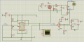
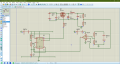
So i am trying to build this circuit using nothing but basic components (RLC) with a 555 timer for the PWM and Op Amps for feedback to ensure it is regulated. It needs to be able to take an input of 20V +- 4V and output a steady 5V@0.5A. My idea is to take a voltage divider at the buck converter power stage output and feed it along with a constant reference voltage to an op amp to amplify the error. Then that signal would be put into pin 5 of the 555 timer to control the Duty cycle. I have attached my circuit and I am unsure why Proteus is giving me logic 0 throughout the circuit and not functioning the way i intend it too. Any ideas on how to fix it would be greatly appreciated. I will attach my schematic as a screenshot.
Attachments
-
 149.5 KB Views: 63