I could try winding my inductors. That's a good idea.
I'm going to draw up a schematic of my idea (using an external op-amp) and see if it will work. I have a fried multimeter with a 0.01 ohm current shunt in it, so I'll use that.
Inductors are one of the few components it is practical for a home hobbiest to make. They can be as high a quality as commercial models, but you do need to do some reading for some of the pitfalls. It is a part I keep coming back to now and again, I'm about to start my yearly cycle on another thread.
As for the design Wook and I came up with, here is a preliminary sketch. Now I need to build it to verify it. Use Windows Picture & Fax Viewer to print it for full effect.
I'm not certain on the choice of MOSFET in this case. The VP2206N3 in a TO-92 package, with θJA at 125°C/W, this means your transistor will only be allowed to dissipate about 1W in ambient air at room temperature (about 1 amp drain current.) Although this exceeds the ~640mA rating, it would probably dissipate more when switching. Can someone clarify the choice of FET? I think the FET will last *much* longer if you clip one of those TO-92 heatsinks on it.
Or I could use the parts I have, and see what happens.
Earlier in this thread we discussed parts, and I agree this is not the best I can get. However it was what the local stores had.
The good news is, if it works with this, it will work with just about anything.
The coil was off putting too, since there really isn't a standard layout for a part like this.
I really think this MOSFET is pretty bad. If a MOSFET is run properly, and has a low on ohmage, it will stay cool. It is one of the advantages of using a MOSFET in a switching power supply. Like I said, I'll let you know how it works out.
I'll predict that the MOSFET will be a crispy critter within a minute of power-on.
I could not simulate the circuit with any degree of accuracy, as I did not have a P-ch power MOSFET with specifications anywhere near as bad as that one has.
However, earlier today I sent Bill some reinforcements. Didn't send any P-ch MOSFETs, but plenty of other stuff to experiment with; quite a few things related to this thread.
Bill is one of the hardest-working contributor on the forums - not to slight other contributors, of course - we have quite a number of them; too many to mention. He just works at it a lot harder than most. I appreciate that.
Much as I would love to argue about the probable outcome of the MOSFET, I don't think I can. If it works it will be a pleasant surprise. We shall see. I have some decent LL (logic level) n-channel types, but LL p-channel are just plane harder to get.
I'm trying to keep my skills sharp, there is bound to be a decent job sooner or later with my name on it. That and it is my idea of fun.
Before I could afford a decent parts stock you should have seen some of my experiments, especially with RF oscillators. Toilet roles make decent inductor forms. It was pretty lame, but if my Dad told me to turn it off I had succeeded.
I made my first crystal radio using a toilet paper roll as the form for the inductor. Wound on a bunch of turns of AWG34 magnet wire.
Anyway, Monday you'll have a bunch of MJD32's, so you could use one of them as in the attached schematic. Won't be as efficient as a MOSFET due to Ib, but that's life.
You could also use one of the MJD117 Darlington's and get rid of Q2, R6, R7, and change the values of R4/R5 to sink 2mA via the base; you'd have ~1.2Vce, but that would be OK. You would then be limited to around 1A output current due to the Darlington.
Bill, any idea on what voltage that version runs from? 7V to 20V would be ideal. I'm considering drawing up a PCB for a 9V powered version, using SMT components and a smaller surface mount FET (less current rating, maybe 500mA.) It could be a project for me to do. One of my original ideas was a constant current LED tester based on an op-amp and NPN pass transistor, but as you can imagine, that would not be very efficient.
I'm currently developing another version of my original Buck LED Converter. This uses essentially the same principle (gating an oscillator in a feedback loop) but will have a few changes. The prime changes are:
Entirely op-amp based. Op-amp is currently undecided
N-channel MOSFET for power switching device
Slow start
Being op-amp based leaves me with a few problems. This version is based on an undecided op-amp due to the relaxation oscillator and the slow start (which are combined into one.) I need an op-amp which will produce a 10% duty cycle square wave at up to 15 KHz with acceptable skew rate (preferably less than 5% of the wave period.) Does anyone have any suggestions?
An N-channel MOSFET is used. Because there is an on board oscillator, the oscillator is also used to provide the boost voltage for the gate pin (approximately 16 volts relative to ground; the LED drops 2-3 volts, so this is *about* 13-14 volts Vgs, which is enough to put a non-logic FET easily into saturation, right?)
Slow start is also implemented. This consists of lagging the oscillator, so the output ramps up from around 200mA to the maximum in about 100 milliseconds. The slow start is implemented by shifting the virtual ground for the relaxation oscillator. Slow start is also used on the comparator (+) pin to further delay ramping, preventing damage to the LED.
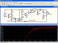
In the prototype I show here, I have replaced the MOSFET with an analog switch, but it is close enough for now. The on resistance of the switch is set to 0.01 ohms. I would like some feedback on how to drive the FET, since I have this high Vgs voltage. Also, the AND gate will be replaced by some discrete logic when I have finished the logic.
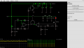
Paste this code into Falstad's circuit simulator (falstad.com/circuit) and have a look.
Rich (BB code):
$ 1 5.000000000000001E-7 6.724437240923179 50 5.0 50
172 768 368 800 368 0 6 0.01 0.01 0.0 0.0 0.5 Voltage
r 848 336 848 400 0 0.01
g 848 400 848 416 0
l 656 224 720 224 0 4.7E-5 1.1424579216893314
d 656 272 656 224 1 0.3
c 720 272 720 224 0 0.0022 -2.131877625920294
162 848 224 848 272 1 2.1024259 1.0 0.0 0.0
159 480 224 512 224 0 0.01 1.0E10
R 144 224 112 224 0 0 40.0 15.0 0.0 0.0 0.5
150 496 352 496 272 0 2 0.0
w 512 224 656 224 0
w 496 240 496 272 0
g 656 272 656 288 0
l 720 224 784 224 0 4.7E-6 1.017274131199679
c 784 224 784 272 0 4.7E-5 2.112582196613325
w 784 224 848 224 0
r 768 368 688 368 0 10000.0
c 688 368 688 480 0 2.2E-6 0.008681254288512305
g 688 480 688 496 0
a 624 352 512 352 0 15.0 -15.0 1000000.0
w 848 336 624 336 0
w 848 336 848 272 1
r 624 368 624 480 0 100000.0
g 624 480 624 496 0
w 624 368 688 368 0
a 320 352 432 352 0 15.0 0.0 1000000.0
c 320 288 224 288 0 1.8E-10 0.5144001826132245
r 320 288 432 288 0 100000.0
w 432 288 432 352 0
w 320 336 320 288 0
w 320 368 320 416 0
r 320 416 432 416 0 100000.0
w 432 416 432 352 0
r 320 416 224 416 0 100000.0
w 432 352 480 352 0
r 176 336 176 416 0 47000.0
r 176 416 176 496 0 47000.0
c 224 416 224 496 0 2.1999999999999998E-4 0.13076111194300727
g 176 496 176 512 0
w 176 416 224 416 0
w 144 224 176 224 0
w 176 224 480 224 0
w 176 224 176 336 0
w 224 416 224 288 0
g 224 496 224 512 0
g 720 272 720 288 0
g 784 272 784 288 0
w 432 288 432 176 0
w 512 48 512 32 0
w 512 32 176 32 0
w 176 32 176 224 0
t 464 64 512 64 0 1 -14.843168833097234 -0.6447190762854645 100.0
t 464 128 512 128 0 -1 0.1568311669027659 -0.6447190762854645 100.0
r 432 176 432 96 0 1000.0
w 432 96 464 96 0
w 464 96 464 128 0
w 464 96 464 64 0
d 512 32 576 32 1 0.805904783
d 576 32 640 32 1 0.805904783
c 576 32 576 96 0 9.999999999999999E-6 13.496166052807856
w 576 96 512 96 0
w 512 96 512 80 0
w 512 112 512 96 0
g 512 144 512 160 0
c 640 32 640 144 0 1.0E-6 25.736795068834795
g 640 144 640 160 0
z 704 144 704 32 1 0.805904783 16.0
g 704 144 704 160 0
r 640 32 704 32 0 680.0
O 768 32 816 32 1
c 768 32 768 144 0 1.0E-6 16.069480834640004
g 768 144 768 160 0
w 768 32 704 32 0
o 15 64 0 289 1.3701039886888295 1.7537331055217023 0 -1
o 32 8 0 43 20.0 9.765625E-5 1 -1
The SMPS stage (inductors, capacitors, diodes) remains virtually unchanged from the original version; they seem to work well.
In this image the SMPS is trying to output 1 amp constant current through the red LED, that's about 2W.
N channel is probably a non starter. There is a reason Wook and I are going with p channel. Basically the amps (the comparators) sense near their ground connection. It doesn't work the other way well. Even op amps have this restriction, and you will need a high speed op amp for it to work. Speed comes with comparators as a given.
I made the 0.1Ω current sense resistor. It drew 0.85A with 0.1V across it, which puts it at 0.118Ω.
I cut 12 ¼" of 30 gauge wire wrap wire, then folded it until it was just under ½" long, then shrank some heat shrink tubing around it.
Less than 0.1Ω (such as 0.01Ω) is also going to be a problem, since you are approaching the resistance of the leads and wires within the circuit.
Well, another of the reasons a P-ch version was attractive is that high-side current sensing can get a bit hairy. Commonly used comparators can "see" down to ground, but don't handle inputs within ~1.5v of +V very well; they don't see them at all.
The idea was to make a fairly easy circuit where most of the stuff could be obtained locally, and at the same time, it would be pretty efficient.
But, I just don't have a P-ch MOSFET on hand that really satisfies all of the requirements of this project - and I completely forgot to check my favorite local electronic goodies store to see if they had anything suitable. Most of what they carry is surplus from electronic manufacturers. I've found some N-ch logic level MOSFETs, but not many.
P-ch works OK for low-power stuff, but once you start getting into more than a few amps current, N-ch is really the way to go. Otherwise, you wind up with a really large gate charge penalty; about 2.5 times as much as an equivalent N-ch MOSFET.
N channel is probably a non starter. There is a reason Wook and I are going with p channel. Basically the amps (the comparators) sense near their ground connection. It doesn't work the other way well. Even op amps have this restriction, and you will need a high speed op amp for it to work. Speed comes with comparators as a given.
I made the 0.1Ω current sense resistor. It drew 0.85A with 0.1V across it, which puts it at 0.118Ω.
I cut 12 ¼" of 30 gauge wire wrap wire, then folded it until it was just under ½" long, then shrank some heat shrink tubing around it.
Less than 0.1Ω (such as 0.01Ω) is also going to be a problem, since you are approaching the resistance of the leads and wires within the circuit.
The current shunt is still on the low side even though the power device is a n-channel MOSFET. With limited other components it could be replaced with a NPN darlington, like the TIP122, in my original circuit.
If the current shunt is directly connected to the comparator ground then shouldn't the resistance of the connecting wires only affect efficiency, not accuracy? I have a burned out meter with a 0.01 ohm shunt in it, I desoldered it and soldered some wires on it, so I'll see how it goes.
Well, another of the reasons a P-ch version was attractive is that high-side current sensing can get a bit hairy. Commonly used comparators can "see" down to ground, but don't handle inputs within ~1.5v of +V very well; they don't see them at all.
The idea was to make a fairly easy circuit where most of the stuff could be obtained locally, and at the same time, it would be pretty efficient.
But, I just don't have a P-ch MOSFET on hand that really satisfies all of the requirements of this project - and I completely forgot to check my favorite local electronic goodies store to see if they had anything suitable. Most of what they carry is surplus from electronic manufacturers. I've found some N-ch logic level MOSFETs, but not many.
P-ch works OK for low-power stuff, but once you start getting into more than a few amps current, N-ch is really the way to go. Otherwise, you wind up with a really large gate charge penalty; about 2.5 times as much as an equivalent N-ch MOSFET.
That's precisely why I want to use an n-channel FET. But current sensing is on the low side and this seems to work well. Why can't you do current sensing on the low side with MOSFETs?
I was thinking of a TL072/82/92 dual op-amp. Does anyone know if this would work well?
What we are talking about with the MOSFETs is how the switching action works. You want a transistor that operates withing the power supply levels. A n channel uses positive voltage to turn on, a p channel uses negative voltage with respect to the drain. If you have a series pass transistor on the positive rail you don't want to use more positive voltage greater than the power supply to turn it on.
Your schematic doesn't show any MOSFET, try working on it and the logic will become clearer.
The current shunt is still on the low side even though the power device is a n-channel MOSFET. With limited other components it could be replaced with a NPN darlington, like the TIP122, in my original circuit.
If the current shunt is directly connected to the comparator ground then shouldn't the resistance of the connecting wires only affect efficiency, not accuracy? I have a burned out meter with a 0.01 ohm shunt in it, I desoldered it and soldered some wires on it, so I'll see how it goes.
Trouble is, if you have the current shunt between the source terminal of the N-ch MOSFET and GND, you'll only "see" the current while the MOSFET is on. This results in a rapid escalation of current until something emits smoke.
re: P-ch vs N-ch gate charge
That's precisely why I want to use an n-channel FET. But current sensing is on the low side and this seems to work well. Why can't you do current sensing on the low side with MOSFETs?
The current sense shunt would need to be in the LED's current path. You might be forgetting about the "flywheel" diode that keeps the current flowing through the inductor and LEDs when the MOSFET is off. The sense shunt needs to be in that loop somewhere.
I was thinking of a TL072/82/92 dual op-amp. Does anyone know if this would work well?
The TL07x and TL08x, like the LF353, cannot "see" within 1.5v of +V, or within 3v of -V. They would not work well at all for current sensing in a single-supply circuit for that reason.
I was not familiar with the TL092 opamp; it does look like it will sense to the negative rail - so that might be an option. However, being an opamp, it's bandwidth will be more limited than a comparator that was designed to be operated open-loop.
I suspected the loop (freewheeling diode, inductor and capacitor) could be an issue. Would the 0.01 ohm low side shunt work if all grounds (on the power side) were connected through this?
I'm a complete noob at SMPS design so sorry if what I say is making sense.
I suspected the loop (freewheeling diode, inductor and capacitor) could be an issue. Would the 0.01 ohm low side shunt work if all grounds (on the power side) were connected through this?
I'm a complete noob at SMPS design so sorry if what I say is making sense.
The current sensing portion needs to report to the current control/switching portion what the actual current flow is through the load at any given point in time.
If you have an alternative current path that is not accounted for (such as the freewheeling/flywheel diode, or perhaps a synchronous switch used as an "ideal diode") then you will wind up not accounting for all of the current. This error can become very significant if you are using an inductor in continuous current mode (the inductor current never drops to zero); approximately 1/2 of the load current will not be measured.
There is a related problem when one attempts to use a single low-side current sense resistor in an H-bridge.
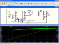
Here's a version using a small PNP Darlington; an MPSA63. That transistor is good for up to around 500mA, but better to limit it to 300mA. An MPSA64 is rated for up to 1.2A, but it would be good for perhaps half that.
I changed the power source to ramp from 0v to 24v; you can see that the LED doesn't start getting current until the power source is around 8v, but it's pretty constant current from 8v to 24v.
I changed R2 and R3 to make the maximum current limit 100mA; as when I breadboard the thing I'll be using an LED rated for 70mA.
The comparator has been changed to an LM111; a high-reliability equivalent to an LM311 - although a single channel from an LM393/LM2903 or LM339 would work just as well. Note that the open emitter of the LM111/LM311 must be grounded for it to work.
R4 & R5 have been adjusted upwards to sink less current from the Darlington's base. L1 has been decreased to 50uH, as the frequency is much higher now; around 160kHz.
A logic-level P-ch MOSFET would eliminate some power loss from Vbe during saturation, but it's not too terrible with the Darlington.
[eta]
Re-ran the simulation for 25mS and a slower rise time for Vcc; note that it starts working at around 4.2v now; exceeding Bills goal of 6v-24v.
[eta] Oops - power dissipation in the Darlington gets to be excessive when Vcc is above around 14v. So, simply using a Darlington is not going to work very well.
 Facebook
 Google
 GitHub
 Linkedin

")