Buck converter based LED power supply

Thread Starter

tom66

Joined May 9, 2009
2,595
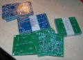
Okay, sent it off for production. Also, here are the gerbers for the V5B design, if anyone's interested in them. Public domain.

I'm also interested in the progress of the design Bill and SgtWookie have been working on. How's that going? This is more of an offshoot, given that it is a synchronous design based around many discrete ICs, whereas theirs is based around discrete circuitry.

If anyone wants any more files, let me know - I'll release them all as public domain.
 

Attachments

SgtWookie

Joined Jul 17, 2007
22,230
Well, Bill had a layout going and was going to etch a board back on page 15, but he seems to have had his hands full with other stuff the last few months. I don't know what happened.

L. Chung had an interesting variant of The_RB's proposal back on page 17, here:
http://forum.allaboutcircuits.com/showpost.php?p=298935&postcount=172
...that could work pretty well with perhaps a refinement or two; right now it would be a bit dicey for a n00b to figure out what to change where in order to get the desired current for their particular LEDs.

I don't have any high-power LEDs to experiment with. Suppose I could just string some standard silicon LEDs in series, or use a Darlington to simulate an LED. But, I'm kind of in a time crunch myself; haven't had a lot of time for the board lately.
 

Thread Starter

tom66

Joined May 9, 2009
2,595
I don't have any high-power LEDs to experiment with. Suppose I could just string some standard silicon LEDs in series, or use a Darlington to simulate an LED. But, I'm kind of in a time crunch myself; haven't had a lot of time for the board lately.
Well, as it's a constant current supply I will just be using an ammeter shunt to measure the current. A multimeter with a 10A range is ideal. That won't test its high range voltage capability though - I purchased some 3W 4.2V green LEDs for this (they are incredibly bright - painful to look at) so I'll test the design with that I suppose, after I verify it's not going to toast the LED.
 

Thread Starter

tom66

Joined May 9, 2009
2,595
Just thinking a bit more about the LED thing - what about using a power resistor? It's not got a non-linear response like an LED, but I don't think that will matter too much. I've got a few 25W resistors, including a 3.3 ohm resistor which approximates a 5W LED. I'll use an ammeter and voltmeter to check the supply, as well as a scope to verify ripple.
 

Thread Starter

tom66

Joined May 9, 2009
2,595
Hi all,

PCBs arrived today :).

Anyone want one? I've got 10. Pay shipping and I'll send one of them free. I have no need for all of them. I have most of the components here to make them, but not all of them, so I need to buy those soon.

I'll have to test them later, but they look good :).
 

Attachments

JMac3108

Joined Aug 16, 2010
348
Tom66,

I applaud your effort and tenacity to design this circuit. If you're using this as a learning process, then go for it. If you plan on using this in a real product, then I would like to point out that there are many very simple chips out there designed for driving constant current into LEDs. Most are switching regulators (buck), designed to provide constant current. Check out Linear Tech - I've used many of their parts to drive LED backlights in displays. They are easy to use, efficient, and extremely reliable.
 

Thread Starter

tom66

Joined May 9, 2009
2,595
Tom66,

I applaud your effort and tenacity to design this circuit. If you're using this as a learning process, then go for it. If you plan on using this in a real product, then I would like to point out that there are many very simple chips out there designed for driving constant current into LEDs. Most are switching regulators (buck), designed to provide constant current. Check out Linear Tech - I've used many of their parts to drive LED backlights in displays. They are easy to use, efficient, and extremely reliable.
Thanks. It's more of a curiosity. I could use an LED driver chip but that's no fun is it ;). Would make it far too easy.
 

SgtWookie

Joined Jul 17, 2007
22,230
Yes, I know this is an old thread, but Bill_Marsden referenced it here:
http://forum.allaboutcircuits.com/showpost.php?p=387467&postcount=6
so it was going to be dug up anyway, and I had something to add.

Bill,
I took another look at the "Bill LED Buck 2" schematic we were discussing on page 7 a year ago, and just wasn't happy at all with the power dissipation in the MOSFET, which was in part due to the Zener, part due to the mosfet itself, but one big thing was the lack of hysteresis in the comparator, which caused a rather wishy-washy toggle of the comparator output. The drive on Q1/Q2 looked like a triangle instead of a square wave.

So, I attacked it and made improvements. Removing the Zener helped the waveform, but adding hysteresis to the comparator turned it into a square wave. I reduced the size of the inductor to decrease the cost; this increased the switching frequency to the range of 190kHz-200kHz. The MOSFET used in the previous simulation is no longer available, but these replacements work better than the old anyway. I swapped out the LM393 for an LM111/LM311. The 2nd comparator wasn't needed, and the LM111/LM311 has far more current sink capacity - even though I'm not utilizing it.

If there is just one LED, the efficiency is around 85%; but with 2 in series, efficiency is nearly 92%.

Q1/Q2 really need a cap across their collectors.
 

Attachments

Thread Starter

tom66

Joined May 9, 2009
2,595
Wow, it's being a long time since I started this project, got PCBs made, then did nothing with them.

Thing is, my PCBs are SMD. That's okay, I've since learned how to do hot-plate reflow - see the pic. That was soldered with some solder paste at 240°C on a hot plate. After I cooled it I went over with it with some solder wick to get rid of all the bridges. But I haven't got any components for these PCBs in question, apart from the occasional resistor/capacitor.

I might try again but using through hole components. Maybe make the design non-synchronous.
 

Attachments

DickCappels

Joined Aug 21, 2008
10,153
I vote for St. Wookie's circuit. Its elegant and probably pretty consistent.

Just to increase the entropy slightly, I adapted a simple current fed buck to drive a 1 watt LED, based on a design by Dhananjay V. Garde in New Dehli. The current can be increased by just making the 2.2 ohm (R1 in the schematic) resistor a lower value and using a heftier inductor. To increase the input voltage, use higher voltage electrolytic capacitors and increase inductance proportionally (use 250 to 300 uH for 12 volts).

It takes few parts to works reliably.


Article at:

http://cappels.org/dproj/1 watt whi...t/1 watt white LED power supply circuit.shtml
[SIZE=+1]
[/SIZE]
 

SgtWookie

Joined Jul 17, 2007
22,230
Interesting, Dick - about 79.5% efficient though. That BUZ73 was really kind of an odd choice; the Rds(on) is high at ~0.6 Ohms, Vdss is 200v, and it is not a logic level MOSFET. It's also switching @ quite a low frequency due to C1's high side being connected on the wrong side of R1 - but the MOSFET turn-off is very slow due to R4 being the only current path from the gate to ground.

I decided the gate drive needed attention, so added an emitter follower pair, which helped a lot. it was operating in the 280kHz range, so I reduced the inductor to 50uH and added an 0.33uF cap from the top of C1 to Vcc, to slow the feedback down a bit. Even with all of that and added parts, the efficiency didn't improve much - but the current through the LED is much more constant.

Now almost all of the power loss is occurring due to R1. Not a whole lot that can be done about that without resorting to an IC, or lotsa parts.
 

Thread Starter

tom66

Joined May 9, 2009
2,595
It seems a lot of these buck converters are based around P channel MOSFETs. The problem with them is the higher on resistance, higher gate charge, higher cost and lesser availability. But driving them is simpler; the gate just needs to be pulled below the source.

This circuit uses a N-channel MOSFET. It uses one LM393/LM339 to generate a clock signal which goes through a push-pull which drives a charge pump comprised of C5, C6, D4 and D5. The charge pump doubles the supply voltage; a MOSFET is limited to about 20V on the gate, so it is clamped with an 18V zener. (I didn't have an 18V zener in LTspice's library, so I used a 10V and 8.2V in series.)

Gate drive requires translation from Vcc to 18V, which is accomplished using Q3. Then Q3 controls a push-pull driver (Q1 & Q2) which pumps charge into the gate. R12 and D10 limit ringing at the gate.

I am using a 6.8V zener to establish a reference voltage. It might be a good idea to move to a 1N4148. The zener was originally going to be used as a virtual ground, however that idea disappeared when I switched from using an LM324 op-amp to an LM339 comparator.

The rest of the circuit is pretty similar. I am simulating an LED as three diodes in series with a 10k to simulate the leakage current. I chose a random NMOS, the circuit would work with pretty much any device. Low gate charge and low on resistance improve efficiency. Inductor and capacitor values probably should be optimised. Low inductance and capacitance values can be used, however, the MOSFET dissipates a lot of heat due to fast switching. This circuit resonates at ~40kHz which gets a good balance between current ripple, efficiency and stability. Also, 40kHz is beyond the range of human hearing, so the inductor won't produce an audible whine.

In the circuit, I am driving an LED at ~2.3V with 742mA of current, or 1.8W. The circuit pulls in around 2.21W, giving a baseline low-power efficiency of 83.7%. I would imagine that optimising the gate driver, inductor, capacitor and diode would improve the efficiency, as would increased output current and higher output voltage. The diode is a substantial hit to the efficiency, dissipating about 0.2W; the other losses come from the MOSFET and shunt resistor. Whilst a lower Vf diode can be used this will always be a big factor in efficiency calculations. Also, don't forget a real-world inductor will have non-zero resistance, so that will drop efficiency too.

Higher input voltage might improve the efficiency too, but going over about 14V gives insufficient clearance for the gate boost voltage, which needs about 4V difference (for logic level FETs.) We could up the zeners to 20V, but we'd be awfully close to breaking down the delicate gate oxide, and I'm seeing many new NMOS devices only rated for about ±18V Vgs. One other thing we could do is move from using a zener from Vbst to ground, and switch it to go from the gate to source pin; however, the zener would add extra capacitance which would probably slow down gate charging.

For some reason, the input current of the buck converter shows thousand-amp spikes on it occasionally. I do not know why; the only thing I can think of is that the diode is still in reverse recovery while the MOSFET switches on, but only occasionally. However diode current is very low, so it might just be a simulation glitch. Adding an Rser to the voltage source (to try and limit these currents) causes LTspice to give up on simulating it.

I am using VirtualBox to run LTspice, which runs okay. But I have a dual core i5 laptop (with hyperthreading, appearing as 4 cores.) So I will try to get VirtualBox to use all 4 cores - there is a way! That might make simulation faster.

.asc file is attached for LTspice. You may also need the LM339 model I used, found here: http://ltwiki.org/index.php5?title=Components_Library
 

Attachments

Last edited:

Thread Starter

tom66

Joined May 9, 2009
2,595
Here's an improved version. This is a synchronous design: it has no diode, instead using a second MOSFET. Making it synchronous is tricky; we have to ensure the two MOSFETs do not simultaneously conduct (which would either destroy them or significantly reduce the efficiency.) I've decided to go with a two comparator solution. One comparator (upper drive) controls the drive MOSFET if the current drops below the low limit; the other controls the synchronous MOSFET when the current increases below the set limit. This gives good dead time, although output ripple and efficiency is reduced, as compared to a dedicated synch driver.

R17 controls the output current ripple although the comparators mainly limit it at this point due to their slow transition time. Maybe a faster comparator should be used.

Also, I've changed the 18V gate generator. It's now got feedback, so the output is regulated to about 18V. There's a clock circuit which can be omitted for Vin > 10V; this pumps the feedback which might otherwise stall when the output doesn't reach 18V. There's the option to increase the gate voltage, at the user's own risk.

There needs to be an undervoltage lock out circuit, as the oscillator locks up, and the MOSFETs and inductor become a linear regulator, at around Vin < 4.5V. Could probably be done with a simple transistor circuit. Also open circuit protection could be implemented, probably again with a simple transistor, set at around 6V.

I got multicore support working in VirtualBox. Win XP shows 2 CPUs. (Doesn't work well with hyperthreading, so stick to 2.) However LTSpice only uses 1. Any idea why?
 

Attachments

SgtWookie

Joined Jul 17, 2007
22,230
Tom,
You're getting slightly less than 81% efficiency out of both of the last two circuits.
Your last one is 3W in, 2.42W out when Vcc=7v (you'd left it set to 5v).

That's only about 1% better than the circuit Dick Cappels posted.

[eta]
Your M2 timing needs work; it's turning on way too late. You're driving M2's gate using Vbst; it should be Vcc instead.
 
Last edited:

SgtWookie

Joined Jul 17, 2007
22,230
OK, did some minor "tweaks" on your synchronous buck, and got the efficiency up to 91.6%.

I changed your three silicon diodes to two high-power LED models that were in the library. They have a Vf of 3.75v @ 1A, so 7.5v total voltage drop across them @ 1A.

Increased the resistance of the pull-up resistors to 1.2k on U1 and U2.
You still have one over in the Vbst section that's 470 Ohms - too low. I suggest you keep your '339 outputs limited to sinking 5mA or less, or you will experience problems with the real parts using them like you are; their output saturation voltage will become excessive, and the transistors you're using to control the gate currents will unexpectedly turn on.

One of the "quick and dirty" fixes was to swap Isetlow and Iset high on the divider, and increase R17 to 300 Ohms. It's very counter-intuitive why I did this; it's because there is no hysteresis on the comparators U1 and U2. Right around the trip point, the comparators are kind of "mushy"; if you want them to "snap" smartly on or off, you need to give them a bit of hysteresis. One way to accomplish that pretty easily would be to put a high-value resistor from one of the comparator outputs to one of the Isets.
 

Attachments

Thread Starter

tom66

Joined May 9, 2009
2,595
Thanks for the improvements. 91.6% efficiency is good.

I've made a few minor changes to the driving circuit (for the MOSFETs) and this gets about 92% efficiency now... not much better really. Right now, we aren't considering inductor switching losses, so this is probably a good upper bound, around 85-90%.

At one point, I had 93% efficiency but current ripple was very high. I added some hysteresis to the comparators, but I couldn't add too much as they became unstable: cross conduction occurred, causing high losses.

Input power: 8.15W
Output power: 7.51W
Efficiency: 92.1%

In terms of losses, we have (% of lost energy):
- Upper MOSFET: 35.1mW (5.5%)
- Lower MOSFET: 31.3mW (4.8%)
- Shunt resistor: 99.2mW (15.5%)

This accounts for only 25.8% of the losses. The shunt resistor is the biggest loss, but using a smaller one would increase complexity as either a lower offset comparator or an amplifier would be necessary. The other losses are:

- R8: 80.7mW (12.6%)
- R3: 78.2mW (12.2%)
- R14: 71.2mW (11.1%)
- R20: 47.9mW (7.5%)
- R15(feedback for boost): 36.1mW (5.6%)
- R11: 31.8mW (5%)
- R6(Vref): 28.9mW (4.5%)
- D3(Vref): 22.8mW (3.6%)
- R7: 22.1mW (3.5%)

These total 65.6% of the losses.
 

Attachments

SgtWookie

Joined Jul 17, 2007
22,230
Well, I started replacing the default "ideal" capacitors with some in the selection list, the inductor with a Coiltronics DR125-101-R, and replaced all of the comparator pull-up resistors' Ohms with {Vcc/.005} and the voltage of V1 with {Vcc}, added a .param Vcc=10 ; this is to ensure that all of the comparators will have to sink no more than 5mA - and got 87.48% efficiency reported when Vcc=10v; 86.6% with Vcc=14v.

However, I kept noticing high current peaks between ~0.4mS-1.6mS; this is occurring because both MOSFETs are conducting intermittently in this time frame. U1's output is the problem. Looks like the comparator is oscillating a bit; instead of a single pulse out, you'll see two, sometimes three compared to U2's output.

Meanwhile, the circuit I posted on page 25 is getting over 91% efficiency even with "real" caps and inductors used; I'd put those in the simulation quite awhile back.
 

Thread Starter

tom66

Joined May 9, 2009
2,595
Interesting. I'm getting 89% efficiency with a non-ideal ideal inductor and 0.01ohm ceramic caps. I was getting the high current peak on start up but found by increasing the capacitor on Iset it eliminated the problem. I'm getting a brief inrush around the start (around 2.5A), but that's probably due to the capacitors being charged.

I'm not well versed in SMPS design. I kinda took a crash course on designing a power supply around an MCP16301 from the datasheet, and I still don't understand it. For example, the inductor doesn't seem to matter that much. A smaller one only reduces efficiency slightly as the circuit oscillates faster. However, I'm sure that selecting the right inductor will improve efficiency.

As can be seen from my tests, the majority of the losses come from the control circuit, the actual SMPS is very efficient. Ignoring the control losses, we'd get 97.9% efficiency, which would be extremely high for a SMPS. A more efficient design would probably use a dedicated control IC, instead of discrete transistors and comparators.
 
Top