Hello, I have built the buck converter exactly as in the lecture example i should get output of 4 Ato 16 A to the output,as shown in the photos lecture file .
Why I get so little current on the load?
Ltspice file is attached.
The simulation is giving accurate results.
You circuit is not "exactly" as the lecture example, since the lecture example had zero inductor resistance.
Your inductor 11Ω series resistance is limiting the current.
How would you expect such a high output voltage/current with that much resistance?
Why is it so high?
You need to think about what component values might do to the circuit when you design it.
Blindly doing a cookie-cutter design is not proper engineering.
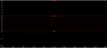
Below is the output with a 1mΩ inductor resistance:
Since in your simulation your inductor has DC resistance (11Ω ) much larger than the load resistance (2.88Ω).
The output voltage will now be equal to Vout = Vin * D * Rload/(Rcoil + Rload) = 40V * 0.3 * 2.88Ω/(2.88Ω + 11Ω) = 2.48V
And this is what you see in the simulation.
Hello ,when I put series resistance 0 then output is 4A,but in the example theory I am supposed to get 16A peaks.
but in the simulation I get much smaller ILpeak.
why is that?
also what kind of realistic diiode should I choose for this purpose?
Thanks.
You are getting Io = I_load around 4A because your load resistance is consuming around 50W.
To get 16A, your load needs to consume 200W (I = 200W/12V = 16.7A).
My observation is that in the REAL WORLD, switcher supplies are quite challenging. That is because every part of the circuit, including every connection, has some effect. That means that in application, to get it right, the simulation must include every bit of the reality. THAT part is difficult to get right.
SMPS live and die from the parasitic elements and the non-linear behavior of components.
As MB2 mentions, to obtain an accurate simulation the model must include at least the major contributors. For an inductor it will be the equivalent series resistance and the inductance drop with an increasing DC bias. There are other effects.
Parts veryseldom fail from overloads or voltage in most simulators. That is handy and convenient but a bit mis-leading at times.
Bob Peasepointed that out years ago.
 Facebook
 Google
 GitHub
 Linkedin