 Facebook
 Google
 GitHub
 Linkedin
I'm new to digital design, teaching myself through AI and books ('Digital Logic and Computer Design' & 'Computer Structures: Readings and Examples'). Progress is slow, and I constantly ask myself, "Am I doing this right?" As you can imagine, it's a little nerve-wracking at times; fortunately, I've broken down my project (a 6-bit microprocessor) into chunks in order to not get overwhelmed.
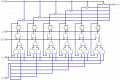
The attached circuit is a 6-bit register, and what I'd like is a critique. Is it understandable? I mean, it's clear to me and the sim but that's a limited audience.
The circuit can be described as follows:
• Z{n} ← 【~RST ≡ 0】 » ↑clk ? ~RST
• Z{n} ← 【M_en ≡ 1】 » ↑clk ? D_in{5:0}
• D_out{5:0} ← 【R/~W ≡ 0】 ? Z{n}
..to translate from my shorthand (heh):
• if ~RST signal is low, on the next rising clock D flip-flop Z{n} then loads ~RST
• if M_en signal is high, on the next rising clock D flip-flop Z{n} then loads bus D_in{5:0}
• if R/~W signal is low, bus D_out{5:0} then loads Z{n}
Attachments
-
 109.9 KB Views: 24


