Just need to know which schematic is the "working revision".
I'm also interested in a Buck/Boost that is essentially a "Joule Theif", but to run a 5W Cree White LED from a Full CR123 cell to dead. See Surefire's "Backup" LED flashlight for the idea, but the two brightness settings from tailcap taps aren't needed (First hit, High, 2nd hit within 1sec = dim, after that, next hit is off). Only requirement is using all SMD components, 1" diameter PCB or less, height can be up to 3/4".
I will later. It's a matter of time, but I may have some free soon. I don't need money, but components would be good. If you have any 0603 resistors, caps, etc. then it will save me the cost of getting them. I can then buy the more expensive components (mosfet, switcher, etc.) myself.
Just need to know which schematic is the "working revision".
I'm also interested in a Buck/Boost that is essentially a "Joule Theif", but to run a 5W Cree White LED from a Full CR123 cell to dead. See Surefire's "Backup" LED flashlight for the idea, but the two brightness settings from tailcap taps aren't needed (First hit, High, 2nd hit within 1sec = dim, after that, next hit is off). Only requirement is using all SMD components, 1" diameter PCB or less, height can be up to 3/4".
C1      100n 0603
C2      22u 16V 1206
C3      100n 0603
C4      330n 0603
C5      100n 0603
C6      100n 0603
C7      1u 16V 0603
C8      4.7u 16V 0805
C9      22p 0603
C10     100n 0603
CONN1   DC power jack CUI PJ 202 - for DC input
CONN2   any 2.54mm 2-way pitch connector, prefer MTA100, can also solder wires to board - for battery input
CONN3   any 2.54mm 2-way pitch connector, small headers only - for PWM input
CONN4   any 2.54mm 2-way pitch connector, prefer MTA100, can also solder wires to board - for LED output
CONN5   any 2.54mm 2-way pitch connector, small headers only - for external ammeter (as a voltmeter)
D1      Any 1.0A Schottky Diode in SOD123 (e.g. RB160M)
D2      Any 1.0A Schottky Diode in SOD123 (e.g. RB160M)
D3      BAV99W SOT-23 dual diode or any SOT-23 diode with pin 1 as anode and pin 3 as cathode
LED1    Any 3mm LED (batt low: recommend red or yellow)
LED2    Any 3mm LED (power: recommend green)
L1      SDR0603-3R3ML or compatible 3.3u >1A inductor
M1      Dual MOSFET N-ch Si4946EY
R1      1k 5% 0603
R2      39k 5% 0603
R3      1k 5% 0603
R4      1k 5% 0603
R5      0R or 4.7R or 10R 5% 0603 (gate leads of MOSFETs)
R6      0R or 4.7R or 10R 5% 0603 (gate leads of MOSFETs)
R7      1.5k 5% 0603
R8      1k 5% 0603
R9      330R 5% 0603 (optional: for low battery LED)
R10     1k 5% 0603
R11     330R 5% 0603 (optional: for power LED)
R12     0.1R 1/3W 1% or 5% 0805 (current shunt: recommend ERJ6BWFR100V)
R13     10k 5% 0603
U1      LTC4442 sync buck controller in MSOP8-EP
U2      LM393 or LM2903 or similar comparator with open collector/open drain (for push-pull version, omit R3) in SO8
U3      TL431 (+/-2% 2.495V voltage ref.) in SOT23
VR1     Bourns 3006P series 1k potentiometer
Q1      SOT-23 NPN transistor, BC847 etc...
Just need to know which schematic is the "working revision".
I'm also interested in a Buck/Boost that is essentially a "Joule Theif", but to run a 5W Cree White LED from a Full CR123 cell to dead. See Surefire's "Backup" LED flashlight for the idea, but the two brightness settings from tailcap taps aren't needed (First hit, High, 2nd hit within 1sec = dim, after that, next hit is off). Only requirement is using all SMD components, 1" diameter PCB or less, height can be up to 3/4".
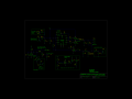
Per thatoneguy's request, I've been working on a design to run a 1W LED from an ultra low voltage. Not a 5W one, but it should be possible to do 5W in future designs with a bigger inductor and beefier components. What makes it remarkable is it can output 200mA into a 3.5V LED at an input as low as 0.9V, and possibly lower in practice. It does require 2.2V to start up, which is its only limitation, but once started, from say 2xAA, it can suck every last joule from the cells.
The design still uses the LTC4442, however, that is a synchronous driver, and this design is not synchronous; it does not use the high side. So in future designs, it will be replaced with a single low side driver, to save space. As it is required to work from ultra low voltages, it uses a boost converter topology; limiting the maximum input voltage to the LED's Vf, but for small voltages of 3V or so, that shouldn't be an issue.
In order to provide the drive for the MOSFET, as well as the supply for the comparator and gate driver logic, a tiny boost converter is used to generate an 8V supply. This converter operates from as low as 0.92V. I'm considering adding space for a 5V LDO (@50mA) to power an optional, add-on microcontroller (on another board), which could control the LED output, if that feature is desired.
With a SOT23 MOSFET and SOT23 driver, it should be possible to fit it in 1" of PCB space. Both sides of the board will be used. I think a bigger inductor will be necessary, but it will probably be eventually capable of driving a 5W LED, though probably not from 1V. Maybe down to 1.5V.
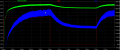
Schematic and transient response to 1V input below (from 2.5V.) The output current does drop to around 200mA, but the LED will still be very bright at about half a watt. Maybe with a different inductor output current can be higher.
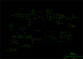
This one is a large input range converter. Meaning, it works from around 10V to 25V. Will probably work at lower voltages, but no guarantee the 7.5V and 5V supplies will remain in regulation. Higher voltages may work, but run the risk of damaging the buck converter's BOOST pin which may not rise above about 40V.
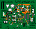
Basically, it's the same converter I originally designed, with a few changes. It's now rated to 1000mA - I've done some simulations, and it should be able to handle this. It's got an input buck regulator, which provides the voltage to drive the MOSFET gates and for the driver chip. It's this which lets it operate over a large range of inputs. It's also got a microcontroller (a small 8-pin PIC12F675) which lets it do funky things like PWM dimming, automatic switching on at dark (there is one spare analog input and one 10k resistor on the board to implement a simple LDR divider), and anything else you can think of programming in it. (The PIC is a DIP type, so a socket can be used and they can be removable. There is also an ICSP socket, if that is required.) For future use I've also included an I2C and 1-Wire bus port (shared pins.) As the PIC needs 5V, there is a 7805 type 5V regulator (which runs off the 7.5V supply.) And to prevent input ringing damaging the supply, there is a 0.47 ohm/0.33W/1206 input resistor in series with the ceramic cap, as recommended by an app-note.
The entire size of the board is 45mm x 36mm. I could have made it smaller, but I wasn't really bothered by it. There weren't many components on this version. And I probably should have made the buck regulator part better, I've done much better before, but since currents are low (<100mA) it should be okay.
The 1000mA output should be comfortably able to drive a 4-5W LED. A small heatsink may be necessary for the MOSFET. Considerable heat removal is already achieved through the use of large copper planes coming out of the fet and some going to the ground plane. The driver may also need cooling if it is found that it gets too hot. However, the fet is rated to 175°C, so it can get pretty hot before we have reliability issues.
It's a simple 2-layer design. If I was bothered by it, I could have designed it on a single layer, but this makes it much easier.
I'll produce this one later, first I will produce the initial non-microcontroller 600mA version. I can get 10 boards made in China for about $20, so if anyone wants one, let me know, and I'll ship one to them free, if they pay postage.
I am also working on Super OSD, so don't have much spare time to devote to this, but I will try and get a working demonstration soon.
That last one is nice, would be better than the regulator I have for my snowblower LEDs (incadescent lights suck in freezing weather with vibration).
The only issue is heat, as in not enough of it. Same problem traffic signs have with keeping the snow melted off the lens. They now use a heater inside, I just need to wait for 5 minutes for the LED to be hot enough to melt any snow covering it.
Trying to come up with some nice headlights for an ATV, they are sold commercially, but the price tag is in the mid triple digits. The design above could be the ticket, I'll need to do some measuring.
candlepower forums has a ton of different buck/boost drivers for high wattage (3-5W+) LED drivers to run from a CR123, building them smaller is the hard part. (yes, I have a flashlight fetish)
Yeah, I've heard of the heat problem. Although an LED is still only 20% efficient (compared to a perfect light source); an incandescent is 1-5% efficient. So a 5W LED will dissipate 4W of that as heat. Nothing compared to say a 20W incandescent which will dissipate 15-19W, but still quite a lot. The driver I designed is a buck converter only, as buck boost are more difficult to design. If I were to design around a buck-boost topology, I'd probably use a dedicated LED controller IC.
Yeah, I've heard of the heat problem. Although an LED is still only 20% efficient (compared to a perfect light source); an incandescent is 1-5% efficient. So a 5W LED will dissipate 4W of that as heat. Nothing compared to say a 20W incandescent which will dissipate 15-19W, but still quite a lot. The driver I designed is a buck converter only, as buck boost are more difficult to design. If I were to design around a buck-boost topology, I'd probably use a dedicated LED controller IC.
This one would be for an ATV, which has a small 12V battery with magneto charging. "Clean" voltage is hard to get, so an input pi filter with inductor and caps would be needed, I'm just jotting down your circuits for ideas to make a "bulletproof" design. If made for winter, it overheats in summer, if designed for summer, snow continually needs to be removed.
Don't go out of the way on this, I'm getting new ideas looking at your ideas is all. I'm interested as well with your OSD project, as I fly R/C too.
This one would be for an ATV, which has a small 12V battery with magneto charging. "Clean" voltage is hard to get, so an input pi filter with inductor and caps would be needed, I'm just jotting down your circuits for ideas to make a "bulletproof" design. If made for winter, it overheats in summer, if designed for summer, snow continually needs to be removed.
The module itself shouldn't overheat. In simulations, the MOSFET (Si4946EY) will hit about 30°C above ambient; which will be hot to the touch, but certainly no where near the maximum 175°C rating, even when taking into account the fact that it could operate at 50°C ambient temperatures. The rest of the board should stay cool. Also, for the input filter I'd advise a TVS in parallel with a zener too (both about 20-25V rated breakdown); the regulator will easily be damaged by input spikes - such an arrangement will remove almost every spike.
I'm sending away for the first revision LED PCB, as well as another project of mine (precision voltage calibrator.) I may also in a week or so send away for the more advanced LED 1000mA converter if I can justify the expenditure to myself. Probably make some garden lights with many of them (one module per light.) The idea is to fit a CdS light sensor to them and write a small program which makes them flicker on as it gets darker. They will all be powered with a 12V 1000mA wall wart in parallel and drive 3W LEDs. If I run the LEDs at 2.5W, I can probably run 4 off one adapter, wouldn't really want to use all 12W as I'm not certain if it will actually meet the nameplate 1000mA rating. Advantage here of using low voltage DC is of course it is much safer if the modules get wet, as opposed to AC mains.
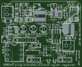
The PCBs take about 3 weeks to get here, though, so don't expect anything soon. The LED drivers should be in red soldermask, because I am trying out SeeedStudio's service with regards to different colour PCBs (so far, only got green.)
I cleaned up the PCB for the 1000mA version a bit more; it now fully passes DRC. I'll probably be sending it off for production along with another PCB of mine. I'm still waiting on the others, I expect them to arrive in a week or two. If anyone has a request for a blank PCB, let me know, I'll send them one if they pay shipping.
 Facebook
 Google
 GitHub
 Linkedin

") We'll see how it goes.
We'll see how it goes.


