Bilge pump circuit for model sailboat

Dirus

Joined Jan 9, 2016
22
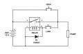
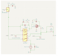
I like the idea Dirus posted in #52. Have not placed a Digikey order yet. I do not mind a more complicated circuit. I can etch my own PCB for it. Can I use 2 pin header pins as the sensors? Digikey has the TIP120.

Before I order, I'll check what I have on hand and list here what I need to order to make sure I have everything.

I'll also try out MrChips simple circuit in #51, but I see there sould be some problems with it from the discussion.

Thank you all for your knowledge!
You can use 2 pin headers, however you don't need to. They're just there to represent the 2 points.

You would use a 2 conductor cable i.e. 24/2 that they use for contacts in alarm systems, one side would be attached to the PCB, the other side would have the insulation stripped exposing the bare wires, tin these ends, and affix the cable at the required location, you could just hot glue it to the side of the hull for example. When the water reaches the bare ends of these wires it creates an conductive bridge between them, essentially shorting them.

Using wires instead of a fixed pin header allows you to fine tune the distance between them to compensate for how clean the water is. Distilled water for example will not work, as its electrically neutral with no minerals or dissolved solids for electricity to flow thru. Lake water is more conductive then tap water etc.

Long term the electrolysis effect will eat the ends of the wire in contact with the water, that's remedied by just replacing them.

A lot of the commercial "leak detection alarms" you find on Amazon for example are just a piece of plastic with 2 "probes" exposed. They work identically to how this circuit works and where I got the idea from.
 
Last edited:

Thread Starter

Ken_NJ

Joined Feb 22, 2021
129
Thanks MC. Will test it out tomorrow.

Dirus, OK on the wires for probes. Tap water will be different from lake water so judging the distance apart will be trial and error. So if you have no mods to your circuit in #52, I'll start ordering parts.
 

Dirus

Joined Jan 9, 2016
22
Thanks MC. Will test it out tomorrow.

Dirus, OK on the wires for probes. Tap water will be different from lake water so judging the distance apart will be trial and error. So if you have no mods to your circuit in #52, I'll start ordering parts.
I'd just set them to work on tap water, if they will work there then they'll work on the lake.

Only mods was as I stated, I incorrectly placed the C1 capacitor on the input side (Pin 1) of the DC-DC buck instead of on the output side (Pin 3). You can place one on each side for even more protection as well, but at the very least it needs to be moved to the output side per the datasheet.
 

B-JoJo-S

Joined Jan 3, 2026
458
Can I use 2 pin header pins as the sensors?
For sensors? Only if you have some electronics to sense the water level. Fresh water doesn't conduct water as well as salt water. You'd need some sort of amplifier to amplify the sensor signal. Using the pins instead of reed switches won't work with just what's shown in post #62. It's a good circuit. But I'm still a little concerned about using reed switches. You have to find a way to float a magnet so it activates the relay.

Also, I'm in favor of the DPDT relay. That way you don't run the risk of burning up your sensors when the motor starts up.
 

Dirus

Joined Jan 9, 2016
22
For sensors? Only if you have some electronics to sense the water level. Fresh water doesn't conduct water as well as salt water. You'd need some sort of amplifier to amplify the sensor signal. Using the pins instead of reed switches won't work with just what's shown in post #62.
I believe he was asking in relation to the 2nd design I posted in post #52, which uses wires as electrodes hooked upto a TIP120 which drives the relay.
 

MisterBill2

Joined Jan 23, 2018
27,921
Consider also that those suggestions that include always powered circuits will have a power drain constantly, which will affect the life of the battery charge, unless they are switched off when the boat is out of the water.
 

Thread Starter

Ken_NJ

Joined Feb 22, 2021
129
Consider also that those suggestions that include always powered circuits will have a power drain constantly, which will affect the life of the battery charge, unless they are switched off when the boat is out of the water.
Batteries are connected, turned on, and systems tested prior to going in the water.
Once done sailing, boat is checked, power turned off and battery disconnected.
Batteries & boat checked again when getting home.

If anyone wants to see some of my boats, I'll post a few pics.
 

Thread Starter

Ken_NJ

Joined Feb 22, 2021
129
I am back on this. Hopefully Dirus is around. I have the circuit Dirus designed from this post.... breadboarded. I don't have S1 and S2 wired up just yet. C1 is 100uf, thats all Digikey had at the time. Otherwise all components are what is in the diagram. Without the electrodes in water, once 8v is applied, the LED is on and the relay is buzzing. I checked the wiring a dozen times, so Im not sure what the problem is.
 

Attachments

Thread Starter

Ken_NJ

Joined Feb 22, 2021
129
No short. I removed D3, the buzzing relay stopped. But the pump activates immediately with the probes out of the water. No change with the probes in the water.

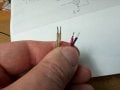
Attached pic of probe ends.
 

Attachments

Thread Starter

Ken_NJ

Joined Feb 22, 2021
129
Reversed D3. That corrects that problem.

Now when power is applied, the pump starts immediately, without probes in the water.
 

sghioto

Joined Dec 31, 2017
8,729
That's normal for the pump to run with the probes out of the water.
I think R2 should be changed to a 470 ohm or smaller for the probes to work in the water.
 
Last edited:

Thread Starter

Ken_NJ

Joined Feb 22, 2021
129
The idea is the pump would normally be off. When the water reached the upper probe the pump would turn on. When the water dropped below the lower probe the pump would turn off.
 

SamR

Joined Mar 19, 2019
5,517
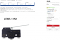
Seal the keel and install a simple micro limit switch with a brass rod and cork. Mount the switch so the lever is down. Attach brass rod to lever. Length of rod as needed. Wine bottle cork on end of rod. No need to complicate things KISS! For example, cheap waterproof micro limit switch... Has both NO and NC contacts. I wouldn't worry about debouncing it either as it won't be used for very long. In fact, why even bother with a float switch? Just turn the bilge pump on when you put it in the water since the battery won't run down in the short time the boat is in the water.
1783644841120.png
 
Top