 Facebook
 Google
 GitHub
 Linkedin
Hello,
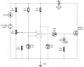
My name is Wan. My focus research area is on Battery chargers. I would like to know the part for Constant Current charging. As i have done a simple circuit for the cut-off battery charger system without constant current.
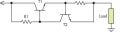
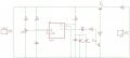
As I have conducted a few testing for the current control it is not constant at all. I am going to charge a 48V 3A 8Ah battery. The charging mechanism should be CC then CV during the end of the charging. I'm using a rectifier AC-DC as input and a voltage cut-off circuit with a current limiter. However, the current limiter is not working as i try to maintain at 3A the current drops while charging.
The input voltage is 56V and the OP-AMP 741 will compare the input if the battery is fully charged at 54V so the OP-AMP will cut off. It is set up by varying the trimmer pot to 54V. My consent is for constant current at 3A, can anyone share with me how to make it constant at 3A.
I am very happy if you can share with me tips or fundamentals for Constant Current Charging/battery charger.
My name is Wan. My focus research area is on Battery chargers. I would like to know the part for Constant Current charging. As i have done a simple circuit for the cut-off battery charger system without constant current.
As I have conducted a few testing for the current control it is not constant at all. I am going to charge a 48V 3A 8Ah battery. The charging mechanism should be CC then CV during the end of the charging. I'm using a rectifier AC-DC as input and a voltage cut-off circuit with a current limiter. However, the current limiter is not working as i try to maintain at 3A the current drops while charging.
The input voltage is 56V and the OP-AMP 741 will compare the input if the battery is fully charged at 54V so the OP-AMP will cut off. It is set up by varying the trimmer pot to 54V. My consent is for constant current at 3A, can anyone share with me how to make it constant at 3A.
I am very happy if you can share with me tips or fundamentals for Constant Current Charging/battery charger.
Attachments
-
 43.3 KB Views: 67
 -
 11.2 KB Views: 70
 -
 91.9 KB Views: 59


")


