Facebook
 Google
 GitHub
 Linkedin
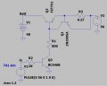
Which version of LTspicce do you use? My LTspice is found missing with a few components such as LM741,FZT751,GP5v1,Rbat,LED.Here's my sim of the circuit with the added current limit transistor.
I modified a couple of the resistor values as needed: and changed the power source for the op amp from the output to the supply voltage.
I also re-arranged the schematic to be in the conventional left-to-right signal/current flow.
The battery is emulated by the 100 Farad capacitor CBat, and resistors RTrickle and Rbat.
Initially the battery charges at the 3A limit (yellow trace) until the battery voltage reaches 54V (green trace), at which point the op amp maintains the voltage at that value, and the current then drops to the 108mA trickle charge current due to RTrickle.
Note that starting at a discharged battery voltage of 44V, the dissipation of Q1 (red trace) is initially 33W, and will require a hefty heat-sink (possibly with a fan) when charging at 3A.
That's why a switching regulator with higher efficiency was suggested for charging.
View attachment 291046
How to set the .ic V(Bt)=44V