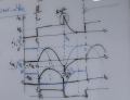
Hello Community, i want to understand the internals of this circuit which are illustrated in this graph (ignore the red curve), i would like to know how the turn off of the thyristor happens
Class B commutation is also called as Resonant-Pulse Commutation. There is only a small change between Class B and Class A circuit. In class B LC resonant circuit is connected in parallel while in Class A it’s in series.
Now, as we apply the input voltage, the capacitor starts charging upto the input voltage (Vs) and Thyristor remains reversed biased until the gate pulse is applied. When we apply the gate pulse, the Thyristor turns ON and now the current start flowing from both the ways. But, then the constant load current flows through the resistance and inductance connected in series, due to its large reactance.
Then a sinusoidal current flow through the LC resonant circuit to charge the capacitor with the reverse polarity. Hence, a reverse voltage appears across the Thyristor, which causes the current Ic (commutating current) to oppose the flow of the anode current IA. Therefore, due to this opposing commutating current, when the anode current is getting lesser than the holding current, Thyristor turns OFF.
The Load plays an important role, since a High Load will take away the Commutating current and prevent Thyristor commutation.
Great i understand now how the commutation work superficially using words, but i want to see the équations that says this along with some interpretation of the latest current/voltage graphs i uploaded, Infinite thanks though
 Facebook
 Google
 GitHub
 Linkedin