AT28C16 EEPROM with 5x7 led matrix Project

Jony130

Joined Feb 17, 2009
5,598
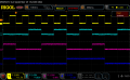
I did the test of this circuit today with NET-74LS93
untdsddditled.PNG

And the diode reset circuit works on my breadboard.

RigolDS3.png

But the reset signal was way too short. So I was unable to capture it on the scope. And this is probably why the short reset pulse is unable to properly trigger the JK flip-flop.
 

Attachments

Thread Starter

q12x

Joined Sep 25, 2015
2,227
But the reset signal was way too short. So I was unable to capture it on the scope. And this is probably why the short reset pulse is unable to properly trigger the JK flip-flop.
Maybe a capacitor to add, to delay it for a bit longer?
Thank you very much for showing me the data ! Very cool that you have a Rigol !
 

Thread Starter

q12x

Joined Sep 25, 2015
2,227
And some big problem: - Tell me if you know about this problem and how to resolve it?
Thank you !
 

sarahMCML

Joined May 11, 2019
698
The clock input of the 4027 is floating, when QA,QB,QC are high.
Connect a pull-up resistor ( for example 4k7) to the clock input.
When I tried it, it didn't work, although I must admit I was using a very old CD4027AE version from RCA.
, not a more modern B suffix type. I found the following to work.
1) Remove the diode from QA and unlink the 2 R0 pins.
2) Reconnect the 2 remaining diodes, with the 4K7 pullup resistor, to 1 of the R0 pins.
3) Reconnect the QA pin to the other R0 pin with a wire link.

That effectively gets you back to the original working AND gate circuit. The problem is the reset pulse at the 8 count is so fast the CD4027 never even registers it (my one at least!)
 

Thread Starter

q12x

Joined Sep 25, 2015
2,227
I remember last night when it worked, I had this arrangement from original experiment.
It was not doing anything important so I remove it today.
I start to believe it was affecting the circuit.
1664125885596.png
All the switches are turn off, and all the addr pins are pull down by those blue resistors on top near the blue DIP switch.
Ive already put resistors to gnd on each addr pin but no effect, it didnt repaired the problem.
Every voltage from (both) 7493 to addr pins are fine, it is counting fine, no problem there.
The memory IC is affected by something....
 
Last edited:

Thread Starter

q12x

Joined Sep 25, 2015
2,227
Nevermind, problem solved - my mistake (as usual) and I find the cause. Thank you for the ideas !
 

Thread Starter

q12x

Joined Sep 25, 2015
2,227
And here I am showing how to program some letters and also switch one after another.
Do take a look at this beauty: aaah
Thank you very much so far !!!
 

Thread Starter

q12x

Joined Sep 25, 2015
2,227
to miss @sarahMCML
I made your circuit and it works ! Better later than never, right?
Thank you very much, miss sarahMCML, I really like it. So the answer why it did worked in simulator but not in reality was a simple wire reconfiguration.
1664144220711.png
Here is what I did and how I did it:
 

Thread Starter

q12x

Joined Sep 25, 2015
2,227
to @Jony130
Your diode circuit will never switch that Clk input of the FF because ...tada, tada, that R1 will always keep it in High state. Hah. I mean, the original thought was to be a pullup resistor. But I bet the FF is seeing it as a input signal always being high. But very curious mister Proteus simulator, did switch it, even if it is always High !!! Probably for him, it is a pullup resistor...hmmm. Eh well.... we learn. At least is counting to 7 ! 50% of the job is done. Heh. We will find a smart way to solve it, Im sure of it.
1664149033381.png
 

sarahMCML

Joined May 11, 2019
698
to miss @sarahMCML
I made your circuit and it works ! Better later than never, right?
Thank you very much, miss sarahMCML, I really like it. So the answer why it did worked in simulator but not in reality was a simple wire reconfiguration.
View attachment 277028
Here is what I did and how I did it:
You must still have a slight wiring error in your circuit somewhere because on mine the last LED ( connected to QD) never turns on, which is correct.
And just our of interest for you, I didn't use a separate NAND gate IC to drive the flipflop, I used a spare AND gate from the CD4081! Saves on IC's and space!
 

sarahMCML

Joined May 11, 2019
698
to @Jony130
Your diode circuit will never switch that Clk input of the FF because ...tada, tada, that R1 will always keep it in High state. Hah. I mean, the original thought was to be a pullup resistor. But I bet the FF is seeing it as a input signal always being high. But very curious mister Proteus simulator, did switch it, even if it is always High !!! Probably for him, it is a pullup resistor...hmmm. Eh well.... we learn. At least is counting to 7 ! 50% of the job is done. Heh. We will find a smart way to solve it, Im sure of it.
View attachment 277029
I just tried Jony130's circuit above with both the CD4027 and a 74LS74 D Type flipflop. The CD4027 doesn't work because the reset pulse is way too fast to trigger it, but the 74LS74 DOES manage to trigger properly, and switch the LED on and off.
 

Thread Starter

q12x

Joined Sep 25, 2015
2,227
I just tried Jony130's circuit above with both the CD4027 and a 74LS74 D Type flipflop. The CD4027 doesn't work because the reset pulse is way too fast to trigger it, but the 74LS74 DOES manage to trigger properly, and switch the LED on and off.
I just look now in my IC list and I dont have your 74LS74. But Im glad it worked, with a special FF then, that was the answer.
VERY interesting !!!! Really - thank you !
 

jjw

Joined Dec 24, 2013
823
to @Jony130
Your diode circuit will never switch that Clk input of the FF because ...tada, tada, that R1 will always keep it in High state. Hah. I mean, the original thought was to be a pullup resistor. But I bet the FF is seeing it as a input signal always being high. But very curious mister Proteus simulator, did switch it, even if it is always High !!! Probably for him, it is a pullup resistor...hmmm. Eh well.... we learn. At least is counting to 7 ! 50% of the job is done. Heh. We will find a smart way to solve it, Im sure of it.
Don't bet too much:)
The diodes will pull the clock input low (~0.7V), when any of the outputs of 7493 is low.
 
Last edited:

sarahMCML

Joined May 11, 2019
698
I just look now in my IC list and I dont have your 74LS74. But Im glad it worked, with a special FF then, that was the answer.
VERY interesting !!!! Really - thank you !
If you have any Positive Edge Triggered 74LS series flipflop IC's in your list, try one of those instead of the 74LS74. Should work!
 

Thread Starter

q12x

Joined Sep 25, 2015
2,227
Project finished.
I disassembled everything from the breadboards.
Target was reached.
Thank you all. What an adventure, right? Haha.
 

dl324

Joined Mar 30, 2015
18,352
What an adventure, right?
Something I designed using a single character display:

Might have to move further away from the screen or blur your vision to see it...

I used a Raspberry Pi Zero W so the time would be set automatically once it connected to the internet.

The row drivers are on 2 boards to the left of the display. Column drivers and counter are on the board to the right.
 

Thread Starter

q12x

Joined Sep 25, 2015
2,227
Very cool mister @dl324 ! I like it. I also like the horisontal scrolling effect. When did you make it?
I believe on a LONG panel the scrolling will be quite 'smart' and intelligible to watch. But on a single matrix appears too fast. But is readable, is fine. Post your circuit please. If you still have it. Or re-make it, just for me. Hehe.
And I waited too long... yes the vertical scrolling that you told me to do it.
 
Top