You know that the output waveform is going to be a sinewave, and now you know its minimum, maximum and average voltages. Isn't that what you wanted to know?
You know that the output waveform is going to be a sinewave, and now you know its minimum, maximum and average voltages. Isn't that what you wanted to know?
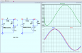
Yes I wanted that but according to simulation in proteus the calculation is shown a bit different.
I at +ve peak it shows 5.05V and at -ve peak it shows 4.92. I am unable to understand this
Yes I wanted that but according to simulation in proteus the calculation is shown a bit different.
I at +ve peak it shows 5.05V and at -ve peak it shows 4.92. I am unable to understand this
I don't understand Proteus, but it does have a sinewave on the input, doesn't it? What do you get if you swap the sinewave input for a +325V DC? or -325V?
I don't understand Proteus, but it does have a sinewave on the input, doesn't it? What do you get if you swap the sinewave input for a +325V DC? or -325V?
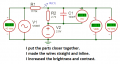
Replacing with Dc I get the results that I have calculated and shown in the images above. Is there by any chance Charging and discharging of capacitor effecting the output voltage?
Replacing with Dc I get the results that I have calculated and shown in the images above. Is there by any chance Charging and discharging of capacitor effecting the output voltage?
Of course it affects the output voltage, since the output voltage includes the voltage across the capacitor and charging or discharging a capacitor requires that the voltage across the capacitor change.
Thanks you very much Ian0, ericgibbs and Wbahn.It really helpled.
I got the values similar in proteus. When I looked in oscilloscope in proteus, I saw the values as I have calculated. The values that I have shared in screenshot were of the voltages at that timestamp.
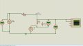
I have a parallel circuit RC circuit connected in series with a resistor R1, Ac voltage is connected to one end of R1 circuit. Dc source is connected to another end of RC circuit. How can we analyse the circuit.
ac voltage-r1-Parallel RC -Dc supply-circuit close.
I want to calculate the voltage across RC circuit.
There are a couple of things we would need to know to get this right, or else we would have to solve for a few different cases.
First, do you want to calculate the AC voltage or the transient voltage?
Second, has the 2.5 vdc source been on for all time or was it just switched on at t=0 ?
This makes a big difference unless you are just calculating the AC voltage. A simulator will give you two different results depending on if you set it to solve for the operating point first or not. If you set it for the operating point first, it will show the AC voltage with a constant DC offset. If you set it to skip the DC operating point it will show a gradual change in the AC and DC voltages, and that is because there are exponential components involved when you skip the DC operating point. This gradual change could be very fast or very slow though depending on the values like the capacitor value.
To help more you should show your results probably in the form of a plot that you are attempting to match.
 Facebook
 Google
 GitHub
 Linkedin
 97.3 KB Views: 4