Very clever mod with the P channel Mosfet. Good thinking you get an A in this course
I was going to suggest using a third transistor for the inversion which also pushes the gain way up meaning slower input changes can be tolerated, but if that mod does the job then that's fine too. Be sure to test in real life too.
BTW, do you need an actual pulse or would just a low going edge work too?
I need a low to high transition, and then remains in high. So, it needs to be a pulse...
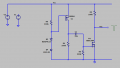
I simulated with slow rising power supply, 4 seconds from 11 to 17V and the pulse is still perfect.
I measured that a difference of 45mV is needed for the first mosfet to switch between power rails.
I need a low to high transition, and then remains in high. So, it needs to be a pulse...
I simulated with slow rising power supply, 4 seconds from 11 to 17V and the pulse is still perfect.
I measured that a difference of 45mV is needed for the first mosfet to switch between power rails.
I am also posting your circuit diagram that has been flipped horizontally. Usually, we show the input on the left and output on the right, although that is not mandatory.
One more small note. It's a good idea to make sure the little arrows on the MOSFETs are shown clearly as that shows everyone what kind of MOSFET it is, P or N channel. If we can not see the arrow clearly, we won't be sure what type it is. I fixed the arrows to make this more clear. We can deduce this from the way it is connected to the rest of the circuit but there could have been a mistake. We can also look up the part numbers which you provided which is a very good idea BTW, but that takes more time.
I searched and it seems that all small power zeners ar rated at 5mA. Or maybe I don't know where to look. Can you recommend me a more suitable zenner ?
I searched and it seems that all small power zeners ar rated at 5mA. Or maybe I don't know where to look. Can you recommend me a more suitable zenner ?
Because my circuit is not working as it should and I don't know what's wrong...
Later I found that some MOSFETs are burnt. Very likely that they burned when I solder them.
I'm tired of MOSFETs... So I converted my schematics to BJT. What I asked in the first post is part of a bigger circuit. I want to buid a CD4013 Latch that swich to 0 logic when the supply voltage si lower than 9V, and back to 1 logic when the voltage pass the 9V and the 15V voltage level. I used @Miso1566 schematic which was posted earlier, but I don't know how to implement the second pulse (at 15V). I tryed like in this example, but I don't think is ok how I connect them in the base of U10... Look at the left part of the circuit, there is the problem. The rest is working normaly...
It's complicated at first glance, but once you understand how it works, it's really simple. Just the left half matters here, up to the zener. There is the circuit that we discussed before. But doubled for 2 pulses...
But the logic doesn't add up. If the circuit produces a logic High at just over 9 volts how to differentiate when it's at 15 volts when the output is already High. What is suppose to happen when the voltage is 15 volts?
The 9 and 15V pulses must appear at the IC clock pin. Data pin is tied to V+, so a pulse there will swich the latch to 1 logic. It is obvious that if the Latch is already in logic 1, the second pulse has no effect. But the thing is that between 9 and 15V you can manually apply a reset pulse (see in the lower middle part of the circuit). And thats why is needed the second pulse.
But the thing is that between 9 and 15V you can manually apply a reset pulse (see in the lower middle part of the circuit). And thats why is needed the second pulse.
No. The 15V pulse must SET the Latch too. The RESET is made from an external source, when the supply voltage is between 9V and 15V. My power supply has a 12V battery and a 16.5V SMPS in paralel by 2 diodes. So I will have 11-13.8V or 16.5V. When there is no line power and the microcontroler see that the battery is almost empty, it resets the latch and shutdown everything. Whe the line power came back, the supply voltage will jump from, lets say 11.5V to 16.15V, and at this point I need the second pulse to swich the power ON.
Now that we're getting more of the story,
Make a separate circuit to detect when above 11 volts and connect the output through a cap to the base of U10 the same as U1 and U7.
Or why is that even needed if it already detects when the voltage is above 9 volts.
It is already done. U7 makes the lower level pulse (at 9V) and U1 make the higher pulse (at 15V). But I don't think that I connect them right in the U10 base... When the second pulse came, by U1, the base is already connected to V+ by C3 capacitor...
This is how it looks like now... In red is the the supply voltage and green is the voltage at the clock pin.
Somehow the second pulse it doesn't seems right... I tried other values for C1, C3, R9, but I can't make it right...
 Facebook
 Google
 GitHub
 Linkedin
")