Facebook
 Google
 GitHub
 Linkedin
Hi !
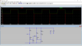
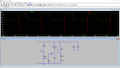
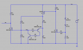
I need to make a circuit that produces a short negative pulse (high-low-high) when the supply voltage rise above 14.5V. The supply voltage vary from 11 to 17V. I found a piece of circuit on the internet which can trigger an repetitive pulse, and I addapt it in simulator to do what I want. I think it can be simplified and optimized compared to how it is now. But as I am not verry good at electronics and I don't really understand how this circuit works, I ask you if you can help me to do it right. The circuit must be verry low power and made only with discrete components (no uC, no NE555). The output stage (R9 and U2 mosfet) and the input stage (D1, D2, R6, U1) should remain as they are. The input stage can be reversed, made with P-Channel mosfet.
I need to make a circuit that produces a short negative pulse (high-low-high) when the supply voltage rise above 14.5V. The supply voltage vary from 11 to 17V. I found a piece of circuit on the internet which can trigger an repetitive pulse, and I addapt it in simulator to do what I want. I think it can be simplified and optimized compared to how it is now. But as I am not verry good at electronics and I don't really understand how this circuit works, I ask you if you can help me to do it right. The circuit must be verry low power and made only with discrete components (no uC, no NE555). The output stage (R9 and U2 mosfet) and the input stage (D1, D2, R6, U1) should remain as they are. The input stage can be reversed, made with P-Channel mosfet.
Attachments
-
 29.5 KB Views: 37
 -
 34.4 KB Views: 37
 -
2.9 KB Views: 3
Last edited:

")