I think I got something... The second pulse is not firm enough because the signal at the transistor that makes it, U1, it has a slower rising ramp (in my simulation) because of R11/R23 divider...
None of the those waveforms actually are correct in my opinion. In reality the output from U10 will go low almost immediately but then rise slower to the supply voltage as the caps charge up.
Like this:
Because my circuit is not working as it should and I don't know what's wrong...
Later I found that some MOSFETs are burnt. Very likely that they burned when I solder them.
I'm tired of MOSFETs... So I converted my schematics to BJT. What I asked in the first post is part of a bigger circuit. I want to buid a CD4013 Latch that swich to 0 logic when the supply voltage si lower than 9V, and back to 1 logic when the voltage pass the 9V and the 15V voltage level. I used @Miso1566 schematic which was posted earlier, but I don't know how to implement the second pulse (at 15V). I tryed like in this example, but I don't think is ok how I connect them in the base of U10... Look at the left part of the circuit, there is the problem. The rest is working normaly...
As they say in some circles, Holy Moly, or just WTF.
I can assure you that is way over complicated.
What you should do it look into what is called a "comparator". This is something like an op amp, except they provide either a logic high or a logic low. You set the trip points simply with resistors and a reference voltage. You can even include a pot so you can adjust the trip points precisely. Working voltages up to 30 volts.
LM339 for example, cheap and easy to use. I am sure people here can help you get started with a design like this. You will find it much, much easier to get it right as this kind of thing has been done for years now using comparators with great success and simple circuits.
I searched and it seems that all small power zeners ar rated at 5mA. Or maybe I don't know where to look. Can you recommend me a more suitable zenner ?
I need 9V and 14.5V... There is no combination I can do with PLVA600 series.
But what would be the advantage of using these zeners instead of the regular ones?
You have to be careful with circuits that rely on zeners and MOSFET gate turn on voltages to achieve accurate voltage trip points. It's usually not a good idea because there is a lot of room for variations which can mess up the trip points.
A more modern way is to ditch the zeners and go with voltage reference diode(s). Even the cheap ones are much better than zeners.
Also, design the circuit so that the MOSFET gets a nice, healthy gate turn on / turn off voltage when the trip point is reached, which is often done with a little hysteresis. What this means is that when the trip point is reached, the MOSFET gate goes from zero to some decent turn on voltage like 10 volts or whatever is needed for that MOSFET, and for turn off the gate voltage goes from 10v down to 0v with a fast transition.
Allowing the zeners and MOSFET turn on voltage to decide when to turn on/off means it could even turn on and off several times before it stops oscillating.
I made the real circuit like this and it works. I had a little trouble with it, because it triggers ON and OFF at parasitic fluctuations in the electrical network. It didn't stop until I put those 20nF capacitors on the IC inputs. But now it's fine. I was verry surprised to find that the Set and Reset voltage level are exactely like in the simulation. No adjustment needed. And that with regular zeners. It draws only 150uA from the power supply when is on battery (<12.5V) and 1mA when is on SMPS (16.5V).
What do you think, those parasitic triggering could it be because I did the circuit in the air or it will do even when I will build it on PCB with ground plane ? Could it be also because my circuit works with verry small currents ? This thing scared me a bit...
Yes, I've done that a few times myself. Usually with much less complicated circuits though.
For example, glue an IC chip upside down onto a sheet of fish paper so the leads are all sticking up, then solder to the leads. Make a note somewhere what chip part number it was.
It's kind of funny too when a run of PC circuit boards is produced and it is found out later a little capacitor has to be added to the circuit. It's then soldered to the back of the board to avoid making all new PC boards.
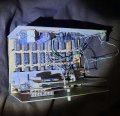
The board was double sided but the wire runs were so complicated I had to use jumpers too.
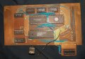
That's nothing though compared to this next project which was an 8-digit frequency counter. All TTL and wired with #32 AWG magnet wire.
If you look at the very left bottom corner, you can see two bundles of magnet wire coming up through the board. There is a LOT more wiring under the board, all magnet wire
Originally it was all original TTL, then some years later I changed the chips to TTL LS type and that lowered the power supply (see heatsink) requirements.
 Facebook
 Google
 GitHub
 Linkedin