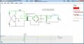
An unusual error in my hacked DMM FS8233

Thread Starter

q12x

Joined Sep 25, 2015
2,227
Why type of SMPS is it, and where does it get its power?
Why not use a small 3vdc wall-wort, which is isolated, for the power?
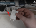
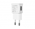
It gets its power from the 240VAC mains. Like I said, it is a 5V SMPS.
1667877881335.png

1667878992704.png
1667878070408.png1667878175742.png
I removed it's USB port and wire directly on the board.
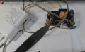
1667878306704.png
That is the VReg board I adapted inside, directly on the 5V output, and from it comes out 3V to the wire.
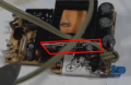
1667878412503.png
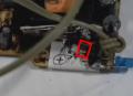
You can barely see a FAT SMD Capacitor... 22uF it was. I have a lot of them (scrapped). It is placed on the 3V Output of this AMS1117 VReg
I didnt put 100nF cap in parallel because space limitations. But I put 2 in parallel on the other side of the wire.
1667878485133.png
 
Last edited:

Thread Starter

q12x

Joined Sep 25, 2015
2,227
IMG_20221108_061242.jpg
Ive just added 5 capacitors in parallel. (its a gray 5th one behind the green one)
220uF - 10uF - 100nF - 150pF - 22pF
Still no effect. The same error.
 
Last edited:

Thread Starter

q12x

Joined Sep 25, 2015
2,227
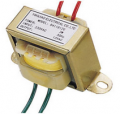
No, that's just a transformer which outputs 12VAC voltage.
I just looked and I dont have a -new- coil transformer. I have 'some' transformers but they are scrapped and I dont know how to find their mains wires. They have multiple wires on both sides, both on the primary and on the secondary. They are special and Im not very sure if they can be converted to my needs. But some look very much like a normal 12V transformer, except having multiple wires both sides.
You would need to add a rectifier, capacitor filter, and a regulator IC to get 3Vdc.
You must reffer most probably to add all these to a step-down transformer shown in the picture above. That is obvious IF I have the transformer ready.
 

Thread Starter

q12x

Joined Sep 25, 2015
2,227
I have a bright idea but I have to simulate it first.
It includes an opamp as a comparator. Fancy !
 

DickCappels

Joined Aug 21, 2008
10,662
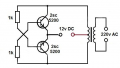
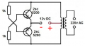
For little things like that I have used a multivibrator to drive a transformer at a decent frequency (over 10 kHz) and then add a secondary that gives me 0.7V more than the required output voltage. The transformer is usually wound on a convenient toroid or pot core.

Ignore the voltages in the schematic below. It is just to give you an idea of the oscillator configuration.
1667899653510.png
Where is says "220v AC" is where (in you case) I would have a winding that gives 3.7 volts, a rectifier and a capacitor. Voilà! There is your isolated DC power source.
 

Thread Starter

q12x

Joined Sep 25, 2015
2,227
to @DickCappels - Thank you very much ! Really ! This looks quite promising and very ingenious ! I understand perfectly what is done here. Is this oscillator legit or is an idea of one? I know the flip-flop oscillator and this is looking like one, but much more simplified. Im not very aware of it to be super sincere. Also... where do I apply the + and - to this oscilator? It looks like both colectors of the Tr's are on + rail. Usually the top rail is + and the bottom rail is the - but at a closer inspection, I see the bottom rail mirroring the top one, meaning that the pozitive current is passing through the bottom Tr's collector and also feeding the base of the top Tr in the same time.
I believe.... this might be the polarity connections:
1667901926350.png
But in the moment 1 of the Tr's is open, a short is created... Very strange circuit.
I believe this is more an idea of an oscillator.
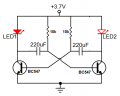
Most probably I should add this classical flip-flop oscillator, powered at 5V and on one of the leds will be the output? That transformer has 2positive and 1 common negative. The hell? Haha.
1667902153150.png
Im not so sure I know how to wire and power this simple one either. How embarrassing. But very interesting electronic puzzle.
 
Last edited:

Thread Starter

q12x

Joined Sep 25, 2015
2,227
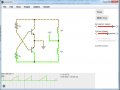
Hold on... I remember I have a simulator so I was right about the polarity from the first shot.
The circuit is indeed oscillating. I didn't consider the coils in my original interpretation. Now it makes sense !
Screenshot_2.jpg
I have little to no experience with transformers. I mean... I know some basics but... still a beginner with them.
Please give me a generalized coil numbers and wire diameter. It would be awesome if you give me some real values, I believe you mentioned you actually built this cct, right? This is COOL ! I love it. Haha. I hope it will do the trick ! It should...
 

Thread Starter

q12x

Joined Sep 25, 2015
2,227
In my updated simulation I observe something interesting...a voltage spike ! The simulation is running at slow speed so I have time to actually read that output voltage. When the other wave is starting, it jumps for a short time to 65V then rapidly going down to a 3V much more stable and longer time voltage. Maybe the capacitor not filtering right? Hmmm... I managed to customize the simulation Transformer parameters to give me 3V at the output. But I get that spike... Probably this transformer is a much more bigger transformer than one built with a ferite core... it must be this particular transformer model causing that huge spike. But I get the idea !!!
Screenshot_3.jpg
 

MisterBill2

Joined Jan 23, 2018
27,998
It is probably NOT POSSIBLE to have adequate isolation from tha mains with anything like a common switched mode power supply. That would include even those certified as safe for medical applications. That is because of the very high input resistance of the DMM analog input circuitry.
I did, at one time a few years back, convert the internal battery powered DMM in one of those "universal lab instruments", to use an isolated 3 volt transformer power supply. The original used a battery for the DMM because they could not make it work with a switcher, and they had no clue about transformer supplies. I used diode shunt regulation for the 9 volt output, along with good filtering, and I grounded the transformer frame to the unit frame. The transformer was SMALL,just over a cubic inch. The result was no more dead batteries, well worth the effort. I don't know what the current draw was, but since it did last many hours on the small 9 volt battery it could not have been much.

So there is a work-around but it does not involve a mains powered switcher. And good luck with that inverter. You will need to ground the core of the transformer, and I suggest a shunt regulator for the output, because spikes are deadly to unprotected analog circuits.
And if mains power is already available, a SMALL commercially made transformer is the way to go. MUCH less complicated.
 
Last edited:

DickCappels

Joined Aug 21, 2008
10,662
The capacitor on the output should take care of the spike if you reference your reading to the negative end of the capacitor.

You can use an off-the-shelf transformer if you can find a suitable turns ratio.

Use plenty of turns on your primary winding to assure oscillation. I would try 20 turns first and see what happens.The isolation is as good as the insulation between the primary and secondary, which can be very good.

By the way, the example circuit used monster sized 2SC5200 transistors. I usually use 2N2222 or other TO-92 transistors. So far I've seen that the high the current rating the lower the VCE saturation Voltage.
 

Thread Starter

q12x

Joined Sep 25, 2015
2,227
I suggest a shunt regulator for the output, because spikes are deadly to unprotected analog circuits.
I very much agree !
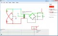
Here is how I resolve it. But be free to correct any mistakes. Im not building these kind of cct's everyday.
I use a 3.3V zenner for the shunt regulator. And the transistors are specified on top.
The graph in the bottom is for the highlighted blue wire. Yes this simulator can graph wires as well, not only components. Very handy.
Screenshot_3.jpg
 

Thread Starter

q12x

Joined Sep 25, 2015
2,227
The extreme accent and very high-speed words drove me away from the video.
At least you are sincere. I speed up all my videos to shorten their length. Its purpose is not to annoy anyone but to be shorter in time length. If I let it on normal speed, it will get very-very-VERY long. So by speeding it up I am making it watchable. But at cost of being a tiny bit fast. It is very comprehensible. You kind of have to adapt to it for a little bit. But hey... thats my point of view.
 

Thread Starter

q12x

Joined Sep 25, 2015
2,227
You can use an off-the-shelf transformer if you can find a suitable turns ratio.
Use plenty of turns on your primary winding to assure oscillation. I would try 20 turns first and see what happens.The isolation is as good as the insulation between the primary and secondary, which can be very good.
Point me which DIMENSION you think is good.
Screenshot_4.jpg
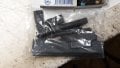
I also have ferrite bars and small cilinders
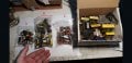
20221109_015806.jpg20221109_015823.jpg
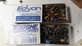
and round cores that I can re-wire them.
20221109_015850.jpg
My friend @DickCappels, point me what is the size that YOU think is good enough to fit 20 turns for primary and ??? for the secondary.
Thank you.
 

Thread Starter

q12x

Joined Sep 25, 2015
2,227
Here is some progress on this circuit Im building with my dear friend @DickCappels
Yah...it's working so far. Im very happy about it. Im Very curious how it will look on the other side of the transformer ! VERY curious.
 

Thread Starter

q12x

Joined Sep 25, 2015
2,227
Very-Very estimatively mister @DickCappels, and it will be good enough for me as a reference point; How many turns on the secondary? Very wild guess. I can not guess anything, I never play that much with these types of transformers. No idea, but you may have.
 
Top