Amplify High frequency microvolts sine wave

Thread Starter

MrsssSu

Joined Sep 28, 2021
266
1665163386971.png1665159446157.png
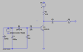
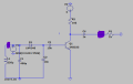
Dear all, I simulated a radio-receiver circuit, where I have actually build a part of the circuit which helps to amplify a sine 550kHz frequency of microvolts (antenna voltage) into several volts, however, I do not see any amplification on the output as highlighted above where I attached a resistor in series with capacitor to act as a DC bias so that the voltage swings around 0V. I am not sure what have I done wrong and I have doubts regarding the use of the diode in this case because the forward voltage drop of diode is about 0.7V normally and this means we should be supplying several volts and not microvolts to the input of the diode. My question is how to amplify a sine 550kHz frequency of microvolts (antenna voltage) into several volts (preferably using transistors and not IC), I have attached my LT Spice file below for edit. I am sorry if this is a lousy circuit build by me but I just want to learn more :)


Thank you all for reading and have a nice weekend ahead:)
 

Attachments

Last edited:

MrChips

Joined Oct 2, 2009
30,714
Rectifier D1 is an AM dectector. In extracts the AF signal while C2 shunts RF to ground.

Q1 is not an RF amplifier. It amplifies the AF signal.

In your circuit, Q1 2N2222 has no DC bias on the base. You have omitted R1 shown in the www.circuitstoday.com schematic.

You cannot test or simulate this circuit with 550kHz signal alone. You need AM RF carrier signal.
 

Thread Starter

MrsssSu

Joined Sep 28, 2021
266
Rectifier D1 is an AM dectector. In extracts the AF signal while C2 shunts RF to ground.

Q1 is not an RF amplifier. It amplifies the AF signal.

In your circuit, Q1 2N2222 has no DC bias on the base. You have omitted R1 shown in the www.circuitstoday.com schematic.

You cannot test or simulate this circuit with 550kHz signal alone. You need AM RF carrier signal.
Hi, I have simulated a realistic AM signal with 10uV received an Antenna but I still don't get the amplified output sadly haha. I have updated my LT Spice file for you to view and edit :)
 

Audioguru again

Joined Oct 21, 2019
6,674
In the other forum about this circuit I said that the RF rectifier diode is missing an important load resistor to ground.
Then the filter capacitor fully charges on the first half carrier waveform and never discharges resulting in no audio output.
 
Top