amp/pwr supply work fine seperate, but not together

Thread Starter

zionarbadon

Joined Jun 10, 2011
52
Hello,
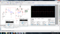
I have been working on a 2 stage amplifier for a project. I have set up the amplifier using a +15V and a -15V battery in multisim. I have it set up to give me the voltage I need across my load.

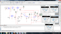
I also have a power supply through a diode bride with a positive and negative rectifier that give me ~+/- 15V.

However, when i take off the batteries and hook up the power supply, my load voltage drops way down. It reads as still putting out the correct voltage off of the power supply.

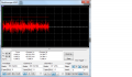
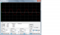
Another thing to note is that with the batteries I get a very nice, non clipped AC waveform. With the power supply I get a very messy waveform that looks like audio waveforms (and since this load is supposed to be a speaker I didn't know if that was right, but I would imagine it isn't).


-Brandon
 

Attachments

Last edited:

SgtWookie

Joined Jul 17, 2007
22,230
Without the schematic of your power supply AND the amplifier, about the only thing we can do is make wild guesses that go on for many replies, yet does nothing to help you solve your problem.

So, to keep the thread relatively short and productive, please post schematics of both your amplifier AND your power supply.
 

Thread Starter

zionarbadon

Joined Jun 10, 2011
52
Without the schematic of your power supply AND the amplifier, about the only thing we can do is make wild guesses that go on for many replies, yet does nothing to help you solve your problem.

So, to keep the thread relatively short and productive, please post schematics of both your amplifier AND your power supply.
Yeah, I didn't know if there was a common mistake or anything easy like that. I've spent so long trying to fix this xD
 

Attachments

SgtWookie

Joined Jul 17, 2007
22,230
What is the current draw from the regulators?

What does the voltage waveform look like on your bridge rectifier filter caps?

It will probably take a number of cycles before the regulator output voltage stabilizes; and I don't see an indication of what the timeline is on your plots. battery voltage is available immediately; but when you are dealing with a simulated power supply, it may be many milliseconds before your output is stable.
 

electronis whiz

Joined Jul 29, 2010
512
it could be that the transformers magnetic field is afaecting it.
this could be because of induction into the amplifier circuit if there close together.
frequincys interfering going from the transformer to the amp through the wires this could be eleiminated by using a filter cap near the transformer or wraping the wires around a toroid then to the amplifer.
the filter caps needing to charge up when it gets turned on
 

studiot

Joined Nov 9, 2007
4,998
With the figures shown I make the conditions at Q2 as follows:

Base divider across 30 volts drops 24 across 4k and 6 across 1k making base at -9 volts.

This sets emitter at -9.7 volts

Thus emitter current = (15 - 9.7)/2 amps

Ouch! :eek:

One very dead 2n3904.

just a question as I don't know Multisim, but you have both rails drawn the same polarity, but labelled one -15 and the other +15?
 

Audioguru

Joined Dec 20, 2007
11,248
A 2N3904 has a max allowed current of only 200mA so it cannot drive an 8 ohm speaker.
An audio power amplifier usually uses two complementary power transistors operating in push-pull.

The input transistors will not work because a resistor is missing that turns off the 2N3904 transistor. The emitter resistor value of only 25 ohms is much too small.
 

SgtWookie

Joined Jul 17, 2007
22,230
Although the 2N3904 transistor is rated for 200mA collector current, you really should de-rate it by 50%, or 100mA. 100mA is no where near enough for your load requirements.

The 78xx and 79xx regulators are rated for a maximum of 1A output. They will shut down if the load exceeds 2A. Linear regulators are not such a good idea to use for high-current loads, as they dissipate a lot of power internally.
 

Thread Starter

zionarbadon

Joined Jun 10, 2011
52
With the figures shown I make the conditions at Q2 as follows:

Base divider across 30 volts drops 24 across 4k and 6 across 1k making base at -9 volts.

This sets emitter at -9.7 volts

Thus emitter current = (15 - 9.7)/2 amps

Ouch! :eek:

One very dead 2n3904.

just a question as I don't know Multisim, but you have both rails drawn the same polarity, but labelled one -15 and the other +15?
I changed it to 15 and rotated it 180 and had the same results.

Anyhow, I must be messin up my calculations big time cause that's not what I was getting, maybe cause I thought I had my beta around 100 (is there a way to check this in multisim?) Anyhow:

Rinbase = B RE = 100x2 = 200
200||1k=166.667
166.667+4k= 4166.667
30/4166.667=7.2mA
7.2mA*4000=28.8V
VB=30-28.8=1.2
and from here i wasn't sure whether to add or subtract .7 o_O
 

Thread Starter

zionarbadon

Joined Jun 10, 2011
52
Although the 2N3904 transistor is rated for 200mA collector current, you really should de-rate it by 50%, or 100mA. 100mA is no where near enough for your load requirements.

The 78xx and 79xx regulators are rated for a maximum of 1A output. They will shut down if the load exceeds 2A. Linear regulators are not such a good idea to use for high-current loads, as they dissipate a lot of power internally.

So I need to start over? xD

I'm confused still as to why it works with the multisim batteries.
 

Audioguru

Joined Dec 20, 2007
11,248
Multisim is extremely STUPID!
It doesn't know that the currents in your circuit are much too high and will burn out your little transistors.

I think you need to learn about an audio power amplifier circuit.
 

Thread Starter

zionarbadon

Joined Jun 10, 2011
52
Thats what's so difficult, I don't know anything about them. I just know basic transistor/amp solving, but the teacher gave us this extremely difficult project and I'm not really sure how to tackle it as we've always been given beta and resistances. I'm just kind of winging it.

Do you guys have any suggestions? I have litterally been working on this for two weeks and its due monday as my final project. :(

Any good sources, suggestions, etc would be extremely appreciated.
 

studiot

Joined Nov 9, 2007
4,998
Looking at post#3

R5 in the first schematic is 2 ohms

R5 in the second is 20 ohms


I purposely posted the guts of my back of envelope calculations. Beta has nothing to do with the static biasing conditions.

I am using the first schematic.

R1 = 4k
R2 = 1k
R5 = 2

Vcc = +/- 15

The voltage divider chain R1, R2 is set across the rails ie 30 volts.

This forces the base to take up the quiescent point at their junction ie 24 volts below the +15 rail ie -9 volts.

This forces the emitter to be 0.7 volts lower ie -9.7 volts.

-9.7 volts is (15 - 9.7) = 5.3 volts above the -15 volt rail.
This is therefore the voltage across the emitter resistor, R5.

Thus the current in R5 is 5.3/2 = 2.65 amps.

Of course you power supply cannot produce this amount of current so the circuit falls over and perhaps your Q2 is not (yet) toast.


Do you guys have any suggestions? I have litterally been working on this for two weeks and its due monday as my final project.
I have to knock off for a couple of hours now but will keep watch over the weekend. I'm sure other here will help meantime.
 

Thread Starter

zionarbadon

Joined Jun 10, 2011
52
For example, any good parts to use would be useful and a good place to read up on audio amps and specifically the circuits/theory. My book is horrible.
 

Thread Starter

zionarbadon

Joined Jun 10, 2011
52
Looking at post#3

R5 in the first schematic is 2 ohms

R5 in the second is 20 ohms


I purposely posted the guts of my back of envelope calculations. Beta has nothing to do with the static biasing conditions.

I am using the first schematic.

R1 = 4k
R2 = 1k
R5 = 2

Vcc = +/- 15

The voltage divider chain R1, R2 is set across the rails ie 30 volts.

This forces the base to take up the quiescent point at their junction ie 24 volts below the +15 rail ie -9 volts.

This forces the emitter to be 0.7 volts lower ie -9.7 volts.

-9.7 volts is (15 - 9.7) = 5.3 volts above the -15 volt rail.
This is therefore the voltage across the emitter resistor, R5.

Thus the current in R5 is 5.3/2 = 2.65 amps.

Of course you power supply cannot produce this amount of current so the circuit falls over and perhaps your Q2 is not (yet) toast.


I have to knock off for a couple of hours now but will keep watch over the weekend. I'm sure other here will help meantime.
I didn't know that we were allowed to do that as I understood it, the VB voltage is based off of how I posted previously because thats the only way our teacher ever did it. If you can get VB the way that you listed, that will make life a bit easier. That's the kind of information that I'm missing for this project xD
 

Thread Starter

zionarbadon

Joined Jun 10, 2011
52
Although the 2N3904 transistor is rated for 200mA collector current, you really should de-rate it by 50%, or 100mA. 100mA is no where near enough for your load requirements.

The 78xx and 79xx regulators are rated for a maximum of 1A output. They will shut down if the load exceeds 2A. Linear regulators are not such a good idea to use for high-current loads, as they dissipate a lot of power internally.
Those were the regulators specifically suggested by my teacher :(
 

SgtWookie

Joined Jul 17, 2007
22,230
If those regulators were suggested by your teacher, then you will need to limit your amplifiers' output current to stay within your power supply limitations.

The Multisim "batteries" are "ideal batteries" - they will output exactly whatever you tell them to output, at any amount of current just shy of infinity. If you attempt to draw infinite current from a Multisim voltage source (like for instance, drawing a wire across the + and - terminals) the simulation will abort with an error.

[eta]
You can learn a lot about audio amplifiers over on Rod Elliot's pages, here:
http://sound.westhost.com/
Have a read through his Articles table of contents:
http://sound.westhost.com/articles.htm
 
Top