I have a couple of CA3080 OTAs at home. I would like to design an AGC amplifier with it.
Does anyone have an example of AGC amplifier? I couldn't find any example on datasheet.
You need a detector of sorts, half or full wave peak detection with a reference target to control the gain. It's up to you to define the behavior. Fast attack? slow decay?
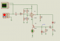
Would you mind sharing some examples? I am stuck in this circuitry down below.
I don't know how to get proper feedback and ablet to adjust the amplitude.
The Question is ........
Do You want to just "use-up" these ancient discontinued Chips on an interesting Project ?,
or,
do You want to build a top-notch Compressor purposefully designed for a specific application ?
.
.
.
The Question is ........
Do You want to just "use-up" these ancient discontinued Chips on an interesting Project ?,
or,
do You want to build a top-notch Compressor purposefully designed for a specific application ?
.
.
.
I am filtering a digital sinewave with a low pass filter. So, the amplitude of the sinewave decays when the frequency increases. So, I would like to keep the sinewave's amplitude on the same level. That's why I needed AGC amplifier. Since I have some CA3080s, I thought i can use them and learn.
If You want to build an AGC Circuit with more modern and less complex requirements,
let me know how much Gain You need to make up the losses that You are currently experiencing,
and also, how fast the Frequency will be changing.
There are probably some guys here that know how to make a CA3080 work,
but that's not me, and I'm not willing to take the trouble to learn how to use an old defunct Chip.
.
.
.
IC2 is a micro computer making a 1khz square wave on pin 5 and a 100khz wave on pin 6.
IC3 is a low pass filter.
Here is the frequency response of IC3 with a 100khz clock. The 1khz will pass and the harmonics will not.
When I did this, I used a 74hc?? frequency counter to divide by 50. I used a different filter IC that had a 50:1 ratio. Then I made just the 50khz signal. The counter makes the 1khz. Sorry I cannot find my schematic.
The point is the filter is not a RC but a digital filter that has a frequency response that tracks along as you change frequency. The output remains constant.
The circuit I used is published in magazines, but I cannot fine it now.
I have a couple of CA3080 OTAs at home. I would like to design an AGC amplifier with it.
Does anyone have an example of AGC amplifier? I couldn't find any example on datasheet.
Basic question: What type of AGC are you interested in?
a) Linear control characteristic with a loop gain depending on signal input power, or
b) Exponential control characteristic ("linear in dB") with constant loop gain?
I am filtering a digital sinewave with a low pass filter. So, the amplitude of the sinewave decays when the frequency increases. So, I would like to keep the sinewave's amplitude on the same level. That's why I needed AGC amplifier. Since I have some CA3080s, I thought i can use them and learn.
If You want to build an AGC Circuit with more modern and less complex requirements,
let me know how much Gain You need to make up the losses that You are currently experiencing,
and also, how fast the Frequency will be changing.
There are probably some guys here that know how to make a CA3080 work,
but that's not me, and I'm not willing to take the trouble to learn how to use an old defunct Chip.
.
.
.
The more current you put into pin 5 the more gain it has, but when you've learned how to use it, the next time you want to make an AGC you might not be able to get one.
So I agree with @LowQCab : Keep the CA3080 for repairing things that have CA3080s in them, and if you want to make a sinewave digitally there are a lot better ways of doing it that trying to chase an ever-decreasing voltage down the slope of a filter.
If you already have a processor, use a look up table and its PWM output. You still need an analogue filter, but the frequency you need to remove is the PWM frequency not the harmonics of the fundamental, and that frequency doesn't change, so your filter response doesn't change.
You would like an AGC circuit that will adjust the gain of a signal generator output over the entire frequency range.
Preferring that also a CA3080 be used comes later. There are many carts that can be placed in front of the horse. A specialized VGA op-amp having wide dynamic range are just some words needed for concept, within a specific terminology.
You can see the effort on this thread to use these terms if there is to be understanding of the concept while adapting and overcoming
the limitations of CA3080.
AN-934 application note figure 1 shows the 4 parts of an AGC. 1 is the controllable gain element.
In figure 2 functional diagram of the AD8336 having 5 blocks connected to pins having labels of sorts.
In figure 5 the complete AGC circuit,
The idea of using a RC filter has problems. amazon This makes a good sine wave generator. Real good for 0-1mhz.
Arduino can talk to it. This and post #9 do not need a VGA to keep the output constant.
Search "DDS Signal Generator Module Board"
I have a couple of CA3080 OTAs at home. I would like to design an AGC amplifier with it.
Does anyone have an example of AGC amplifier? I couldn't find any example on datasheet.
I used a CA3080 IC chip a long, long, long time ago when they were still being made. It was for a solar panel max power tracker. Today I would not use one for anything because they are not being made anymore. That means if something goes wrong with the circuit and you need to replace the IC, you're stuck. Yeah, if you have a bunch maybe it does not matter but I still would not use one.
The data sheet should have information that tells you how to control the gain. The current going into pin 5 controls the gain. From there you can figure out how much current you need to push into pin 5 to get the gain you want.
I think the formula is gm=19.2*i where 'i' is the current into pin 5.
In your circuit, since the output is a current, if you change the value of R5 you will change the overall voltage gain.
 Facebook
 Google
 GitHub
 Linkedin