Hi Steve,
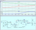
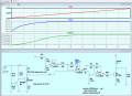
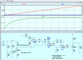
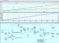
This simulation is based upon your last circuit and description.
I need to know the resistance of the meter and its specification.
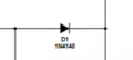
In order to confirm the result, we also need the Diode voltage at 0C and 30C.
E
Getting the diode temps for 0°c and 30°c may prove tricky as it isnt easy to replicate those temperatures at home with any sort of stability. I have a fridge and some rooms. I could possibly see how far down i can get the bottle cooler to go and possibly get 30°c by building a little oven, ive got some 5w resistors and a cardboard box lol.
The meter coil resistance measures at 9.1 Ω after deducting the 0.1 Ω of fluke meter lead resistance.
Which other specs do you need? Ive recorded the voltage input to get the needle to every increment on the scale. 0 is 3.2mv through to 30 at 116mv.
Hi S,
Do you have a domestic temperature thermometer , place the diode and thermometer in a plastic bag, pop it into your home freezer.
Observe the values at 0C..
Heat some water in a cup, use the bagged diode and thermometer to measure temperatures.
E
Sooooo, the readings taken at diode sensor cathode are thus.
2.446v at 0°c and 2.608v at 30°c. (i like the plastic bag trick, seems to stop the temp shooting up or down too fast to take a reading).
I have done away with OA4 and fed the sensor cathode voltages directly into OA2.
ZD1 has been dispensed with and OA1 now fed at 2.445v.
R6 changed from 39k to 1k, and R11 changed from 47k to 2k.
OA3 changed from inverting to non-inverting.
Does it stand a vague chance of working? I have a feeling I am about to learn how close I can get an op amp output towards + supply, but in this simulation OA2 output gets to 3.208v with sensor at 30°c. I am still trying to flog the horse of running it all on 3.7v!
Its hard for somebody new to the concept of op amps to really understand what this all means, but thank you for steering me in this direction. from what i can gather it depends on how high or low the gain is set to? but worse case we are talking in the range of a few millivolts?
I am a hobbyist. I come from a railway electrical background but thats mostly medium to high voltage and lots of relay logic. Electronics although not entirely new to me, is a keen interest that i know little about currently especially when trying to create something from scratch.
60dB ratio? mathematics is one of my worst subjects so no, not really im afraid. keen to learn as always though...

 Facebook
 Google
 GitHub
 Linkedin