Why is what I said not clear???
The circuit is something he grabbed off the net.
The voltage voltage values he wants are different from the circuit posting.
Hi Steve,
Now that it has been shown that the original LTSpice circuit you posted works and gives a linear response over its input/output range, do you now want to discuss a similar LTSpice circuit using your latest input/output circuit voltage requirement?
If yes, please confirm the input/output voltage parameters.
You seem interested in learning LTSpice, so this would be a good way to go.
Hi Eric, that looks an interesting way to go.
Im just in the process of trying to get my temperature probe more stable. I think my previously mentioned accuracy issues are down to the biasing current changing as the temperature increases which is introducing error. I need to attempt to feed it from a constant current source. As soon as I have some better figures, ill get straight back to you.
regards Steve.
Genuine question, but my circuit (an adapted version of your circuit) works equally as well as the latest circuit you posted. Could you tell me what the likely pros are, the reason for the 3rd offset pot and also the idea behind the zener diode?
kind regards, Steve
Hi S,
Your input signal has a range of 0.142Volts, and it is required to raise this range to 1.5Volts.
So the gain of U1 has to be ~10.5.
As the Vsupply is only +5V, multiplying the Vin input range of 0.142v *10.5 = 1.49v, but this would be on top of the 1.225Vmin voltage, this minimum voltage would drive U1 in positive saturation, so U3 is used to generate a a voltage to cancel the 1.225v, thus the U1 voltage output range is 0.1V through 1.6V.
Note: the lower limit of 0.1v is so that U1 is above the 0V saturation voltage.
U2 is an in inverting unity gain amp, so U1 Vout would be + 0.1V through 1.5V
But you want 2.4V through 0.9V, so R3pot is used to shift the Vout up to the required inverted output to 2.4V through 0.9V
The Zener diode is used a reference voltage source for U3 that supplies the U1 inverting with the required offset voltage for cancelling the initial 1.225V part of Vinp.
I will do once i get long enough to sit down and work out how to use it.
In the meantime, my first observation of your circuit is its a hell of a lot easier to adjust than mine!
As an aside, there is a need to limit the outgoing voltage to a maximum. the reason for this is the gauge could end up with 5v on it should the temperature probe become disconnected which would destroy it. could you offer a clue as to the best way of doing this? Dont tell me or draw it, just a clue to help me figure it out. I had thought of using the 4th channel of the quad op amp as a binary comparator and have this control a transistor to cut the load out, but this would obviously cause the gauge to fall to zero where as ideally id like it to stay at full scale until the temperature came back down.
Hi S,
Hint: think resistor and zener on Vout
E
If you told me the purpose of the project, it would make it more interesting.
If you have a drawn draft circuit post it
Here it is drawn on circuitlab as posted previously.
V1 is the incoming signal from a diode temperature sensor and R10 is the load, which in this case is a 0 - 3 kA traction ammeter from the cab of a railway locomotive. As the scale is 0 - 3 I thought it would make an ideal room temperature gauge which can read from 0°c to 30°c as a working ornament. Its full scale needle deflection is around 120mv, hence the circuitry after OA2.
I did try the zener and resister method on my own version of the drawing but it caused the whole circuit to become unresponsive.
Ill have a play with your version and see what it does.
Hi Eric, here is the latest version.
The core circuit is yours so I thank you very kindly for this, it has really helped me to begin to understand operational amplifiers.
I've added other circuits to this and now have a system which appears to work. You may notice the input voltage is now 3.7v. This was done because the USB wall adapters are not really all that stable so I will add a buck converter to the input. Resistances have been changed to suit, and the simulation is performing as it should.
Bottom of the schematic is a constant current source for the diode temperature sensor, D1 being the sensor itself.
The variable resistor and LEDs on the bottom left are for the gauge back-lighting.
AM1 wont be there in real life, I just added that to make it easier to see what was going off in the simulation.
VM1 is the gauge itself, and OA4 is a voltage follower that takes the temperature voltage signal and feeds it into OA3 (I couldn't think of a better way to to do it).
My next questions are, is there anything obvious that jumps out at anyone that may either be breaking convention, or potentially breaking parts? I have successfully simulated complex circuits before only for them to fail or be less than ideal in real life.
Kind Regards Steve
Currently testing the temperature probe around the house and including the fridge.
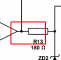
At 6° to 27° we have 2.460v to 2.954v at AM1, 1.300v to 1.166v feeding into OA2, and 1.124v to 2.425v at R13. Once I get the simulation calibrated I should be able to work out the rest for 0°c and 30°.
Just playing around with the simulation to get VM1 pointing at the right things, its very close!
regards Steve
Is your simulation heating the whole circuit though? What is the cause of the problem at VA between 13 and 17°?
D1 represents the temperature probe, but to simulate in circuit lab, I have just been altering the resistance of the diode to give a voltage the same as what the probe on test is providing.
This is certainly different to the results I am getting.
kind regards steve
Hi S,
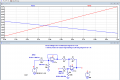
This shows the result ith just the Diode at 0C> 30C.
Do the maths for the voltage inputs of the time 9 OPA and show what the Vout is?
I make hard in negative swing saturation. Vb
What do you measure at the Vout of U2.
Check if my circuit is accurate compared with yours.
E
BTW: Driving a 3.3Vzener via a 1k from a 3.67v supply is not a good idea.
Good evening all.
I stumbled across this circuit some time ago which proved perfect for my own application. I just need a little help fine tuning it.
Could anyone advise on the best order to adjust the four trimming pots?
I am using this circuit to drive a millivolt meter (currently scaled as an ammeter) which gives a temperature reading from a diode temperature sensor.
The operating range is 1.225v to 1.367v input from the sensor and I need a corresponding 2.4v to 0.9v output.
Another circuit converts this into a 0v to 120mv output to drive the dial.
Everything is working fine except it requires some fine adjustment, which I seem to be simply chasing my tail trying to solve.
Not sure if this has been said yet, but there is an industry standard way to handle this, if I understand you right.
What I read here is that you need to have an offset adjustment that can be fine tuned.
The usual way is to just use the arm as the adjustment node point and two resistors connected to the pot. The two resistors limit the range of the pot.
For example, if the adjustment started at +2.5v then the two resistors might be 10k each, with the pot being 1k itself.
It would look like this:
+5v -----R1-----POT-----R2-----GND
R1 and R2 limit the range of the voltage that the arm of the pot can reach. If R2=R1=10k and the pot was 1k, then the center pot adjustment puts out 2.5 volts. If R1=40k and R2=10k then the center pot adjustment puts out roughly 1v.
The adjustment range would be about 5/50=0.1 volts.
The center adjustment is roughly Vcc*R2/(R1+R2), and the adjustment range is roughly Vcc/(R1+R2).
This allows you to set the midrange voltage adjustment and the range of adjustment.
Hi Steve,
I see that what you may have done.
The 2K pot has been adjusted/ changed on your actual project, but the circuit diagram you posted is incorrect.
Look at this version, it needs final adjustment.
E
Note Vvr as per your diagram and the actual value required ie: Vtest.
I suspect you changed the 2.5V zener to a 3.3V version without changing the resistor values.
 Facebook
 Google
 GitHub
 Linkedin
 .
.


