Advice on adjusting op amp circuit pots

Thread Starter

Steve200

Joined Jun 22, 2024
68
Good evening all.
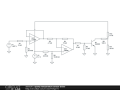
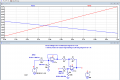
I stumbled across this circuit some time ago which proved perfect for my own application. I just need a little help fine tuning it.
Could anyone advise on the best order to adjust the four trimming pots?
I am using this circuit to drive a millivolt meter (currently scaled as an ammeter) which gives a temperature reading from a diode temperature sensor.
The operating range is 1.225v to 1.367v input from the sensor and I need a corresponding 2.4v to 0.9v output.
Another circuit converts this into a 0v to 120mv output to drive the dial.
Everything is working fine except it requires some fine adjustment, which I seem to be simply chasing my tail trying to solve.

Any help would be greatly appreciated.
Steve.
1719177061347.png

https://forum.allaboutcircuits.com/data/attachments/239/239561-bc63a25e46a09dc38417ae1cf88b35bc.jpg
 

crutschow

Joined Mar 14, 2008
38,325
You need to do more stumbling.
Don't see how that circuit can be perfect, as you need a gain of greater than -1 and its maximum gain is -1 (?).

What's the purpose of the 2.4v to 0.9v output when then you say you need 0-120mV?

Also you should only need two pots for the adjustments, one for gain and one for offset.
 
Last edited:

Thread Starter

Steve200

Joined Jun 22, 2024
68
120mv is the full scale deflection of the guage that is acting as my temperature readout. The circuit I made to get this requires the 0.9 to 2.4v input.
Id thought as well that only two pots were required, but the values on the example circuit attached don't lend themselves to being as such.

I should add that the circuit is fed from a 5v single supply, so I won't be able to get the op amps output down to the correct levels.
I'm using a LM358 dual op amps for this.
 

Thread Starter

Steve200

Joined Jun 22, 2024
68
Hi Eric,
Below is what I have so far. R10 represents the load, V1 represents the input from the temperature sensor.
R's 1,2,5,6 and 8 are variable resistors.
Input is 1.367v at 0°c and 1.225 at 30°c.
The dial requires 2.5mv to show 0°c (its needle rests slightly below 0) and 120mv to show 30°c.
In the simulation, and in real life, the circuit is working in this range, the problems with accuracy occur at readings towards the middle.

https://www.circuitlab.com/circuit/n32z7735pr74/screenshot/540x405/
 

Thread Starter

Steve200

Joined Jun 22, 2024
68
Hi Steve,
I get Error 403 on that link.
I need your LTSpice asc file.
E
Apologies, I've redrawn your original drawing into circuit lab as I'm still in the early stages of getting my head around LTspice. Not ideal, but would a photo help? Alternatively I could draw it in LT spice but I'm not able to simulate it.
 

ericgibbs

Joined Jan 29, 2010
21,395
Hi Steve,
OK, I will create a LTSpice asc file from your post #1 image.
Will post when done.
E

BTW@ I thought you would be punting on the Isis on this Sunny day....;)
 

ericgibbs

Joined Jan 29, 2010
21,395
Hi S,
This is a simulation sim of your original circuit.
You state 0.8V thru 4.2V to be converted to +2.5v thru 1.1v , is that correct?
E
EG57_ 1836.png
 

Attachments

Thread Starter

Steve200

Joined Jun 22, 2024
68
Here you go, i should really learn to use LTspice.
Punting on the isis? Afraid not, im rather poorly at the moment but this is happily keeping me occupied!
temp circuit.png
 

Thread Starter

Steve200

Joined Jun 22, 2024
68
just to be clear, this is my working (sort of) circuit with the resistor values as fitted to the board.

The value of R4 differs somewhat to the example which is how ive got it to work. what im also unclear about is the variable resistors. What would a procedure be to accurately set them up? once we have a little more accuracy (if possible) i can change the other variable resistors to fixed.
the gauge im using is linear, so accuracy is poor most likely because im not setting them up correctly
 

Attachments

Top