AC current measurement - Urgently help nedded

Thread Starter

mishra87

Joined Jan 17, 2016
1,034
Hi All,

I am trying to debug the AC current measurement.
Could anybody help me out.

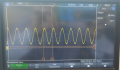
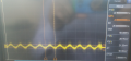
The differential signal across 22R is 50mv for 820mA AC load. Waveform is attached.
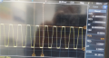
Now if i measure the output signal at opamp output at pin no.4 of MCP6001UT i found 3.3V square pulse.
I checked the signal at pin no 1 of opamp it is the same as output.
I checked the signal at pin no 3 of opamp it is the same as output.

Our idea do design this circuit was we have given DC biasing to 1.65V and AC should be superimpose to DC and then we can get output from opamp pin-4.
But this idea is not working at all.
Current transformer - https://www.promelec.ru/pdf/AC-1020_Jun-06.pdf
Opamp - https://ww1.microchip.com/downloads/en/DeviceDoc/21733j.pdf

So please help me.
 

Attachments

Last edited:

Thread Starter

mishra87

Joined Jan 17, 2016
1,034
What you have is not a differential amplifier. Try putting a 47k ohm between the 22R and the inverting input.
Thanks for your valuable reply & time!

Could you explain abit more about the same.
Actually I did not get exactly what you wanna say.

Thanks again !!!
 

DickCappels

Joined Aug 21, 2008
10,153
I missed something in your schematic.

In a unity gain differential amplifier all resistors in the circuit below are equal.
1572859754594.png
Specifically, the ratios or R1 to Rf and R2 to Rg should be very close to equal. Those ratios give the gain of the amplifier. And how closely the ratio match, the better the common mode rejection.

Connect R2 to your offset voltage instead of ground or you can make a voltage divider as you did but the parallel resistance of the resistors in your voltage divider should be equal to R2.

1572860402232.png
Try this. Sorry about the poor schematic quality. The two resistor values are 4.99k 1% and 10k 1%
This should give you unity gain offset by half the power supply voltage
 

Thread Starter

mishra87

Joined Jan 17, 2016
1,034
I missed something in your schematic.

In a unity gain differential amplifier all resistors in the circuit below are equal.
View attachment 190569
Specifically, the ratios or R1 to Rf and R2 to Rg should be very close to equal. Those ratios give the gain of the amplifier. And how closely the ratio match, the better the common mode rejection.

Connect R2 to your offset voltage instead of ground or you can make a voltage divider as you did but the parallel resistance of the resistors in your voltage divider should be equal to R2.

View attachment 190571
Try this. Sorry about the poor schematic quality. The two resistor values are 4.99k 1% and 10k 1%
This should give you unity gain offset by half the power supply voltage
Hi ,

Thanks for your reply.

I tried with 47K connected with inverting terminal and output voltage is 1.69V.
Now still I am not able to see any changes when load is connected and load is not connected.
In both cases output voltage is 1.69V.

I connected 100ohm in place of R2 and I have not connected Rg.

Please guide me a bit more.

Thanks
 

DickCappels

Joined Aug 21, 2008
10,153
Edit:
Please post your circuit with component values at the moment.

You cannot see changes between when the load is connected and not connected -does that mean that even with a load all you see on the output of the opamp is DC (with your scope)?

How much current is on the secondary of your current transformer when the load is connected and how many volts Peak-to-Peak do you want out of the op amp?
 
Last edited:

Thread Starter

mishra87

Joined Jan 17, 2016
1,034
Edit:
Please post your circuit with component values at the moment.

You cannot see changes between when the load is connected and not connected -does that mean that even with a load all you see on the output of the opamp is DC (with your scope)?

How much current is on the secondary of your current transformer when the load is connected and how many volts Peak-to-Peak do you want out of the op amp?
Hi ,

Please find attached schematic.
Sorry for poor visibility.

The same circuit I am testing.
I have connected 200W incandescent lamp in primary for load.

Rest is same as per attachment.

Regards,
Shiv Mishra
 

Thread Starter

mishra87

Joined Jan 17, 2016
1,034
Edit:
Please post your circuit with component values at the moment.

You cannot see changes between when the load is connected and not connected -does that mean that even with a load all you see on the output of the opamp is DC (with your scope)?

How much current is on the secondary of your current transformer when the load is connected and how many volts Peak-to-Peak do you want out of the op amp?
As Opamp MCP6001ut is rail to rail type so output should not be graeter than 3.3Vp-p and this has to be measured by MCU adc pin for 1A ac load at primary .

Regards
 

DickCappels

Joined Aug 21, 2008
10,153
1 A load/ 1000 = 1 ma. 1 ma x 22Ω = 22 mv.
The op amp is configured to give a gain of 1. You should see 22 mv on the output of the op amp when the load is connected.
1572876662354.png
The *gain is R1/Rf. If you want to make the output 1 V P-P change the 47k R1 supplying the signal to the inverting input to 1k. Then the gain will 47x and the output signal will be 22 mv/amp x 27 = 1.03 V/amp.

* I am leaving out the small effect of the 22 ohm shunt resistor to keep things simple.

The gain you want is one that is likely to fill the dynamic range of the ADC without exceeding it regardless of waveform.

Edit: Note, usually you want the + and - inputs of the op amp looking into the same amount of resistance so as to not have a problem with input offset voltage or input offset voltage drift, but given the very small amount of input bias current this op amp has, you probably do not need to worry about that detail. If you go to very large resistances in the input/feedback circuit or change the op amp type you should revisit this assumption.
 
Last edited:

Thread Starter

mishra87

Joined Jan 17, 2016
1,034
I missed something in your schematic.

In a unity gain differential amplifier all resistors in the circuit below are equal.
View attachment 190569
Specifically, the ratios or R1 to Rf and R2 to Rg should be very close to equal. Those ratios give the gain of the amplifier. And how closely the ratio match, the better the common mode rejection.

Connect R2 to your offset voltage instead of ground or you can make a voltage divider as you did but the parallel resistance of the resistors in your voltage divider should be equal to R2.

View attachment 190571
Try this. Sorry about the poor schematic quality. The two resistor values are 4.99k 1% and 10k 1%
This should give you unity gain offset by half the power supply voltage
Even above circuit does not with the same value I tested the same.?
 

Thread Starter

mishra87

Joined Jan 17, 2016
1,034
1 A load/ 1000 = 1 ma. 1 ma x 22Ω = 22 mv.
The op amp is configured to give a gain of 1. You should see 22 mv on the output of the op amp when the load is connected.
View attachment 190578
The *gain is R1/Rf. If you want to make the output 1 V P-P change the 47k R1 supplying the signal to the inverting input to 1k. Then the gain will 47x and the output signal will be 22 mv/amp x 27 = 1.03 V/amp.

* I am leaving out the small effect of the 22 ohm shunt resistor to keep things simple.

The gain you want is one that is likely to fill the dynamic range of the ADC without exceeding it regardless of waveform.
The problem with circuit is I am not getting any 50Hz sinewave at output.
My output is 1.69V dc only.

Thanks,
 

DickCappels

Joined Aug 21, 2008
10,153
You should be getting the same waveform on the output of the op amp if everything is wired correctly. The DC output voltage seems about right.
Edit: The same waveform, but inverted.
 
Last edited:

Thread Starter

mishra87

Joined Jan 17, 2016
1,034
You should be getting the same waveform on the output of the op amp if everything is wired correctly. The DC output voltage seems about right.
Thank you so much for your support.
Thank for being my debugging mentor.
Could you confirm if I am I right direction.?
With below components value I was able to get the output somehow. Attached are the waveform of the same.

R1=1k, Rf=50k

Thanks again.
 

Attachments

Top