How to Detect CT Disconnection in a Leakage Current Measurement Circuit?

Thread Starter

kagoun

Joined Apr 19, 2024
12
Hello everyone,


I'm building a circuit to measure current. The main idea is to use a current transformer (CT) to step down the current and then measure it using three different op-amps with different gain levels, connected to the ADC channels of a microcontroller. The goal is to detect leakage current. So far, everything is working conceptually.


However, I have a concern regarding a specific edge case. Since the purpose of this circuit is to measure leakage current, when there is no leakage, I expect the ADC readings to be close to zero. But if the CT wires are accidentally disconnected, I will also read zero from the ADC. My question is:
How can I distinguish between these two scenarios (no leakage vs. disconnected CT)?


Is it possible to detect this difference purely in software, based on what the ADC sees, without adding extra hardware to the circuit?


I haven’t built the circuit in real hardware yet, so I’d like to analyze this aspect first before proceeding.


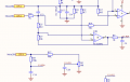
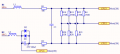
Also, I have a sample project that seems to handle this. I’m attaching pictures of it below. In particular, I think the U1-P30 pin might be used for this purpose. The CT is connected between SP16 and SP12.


Any ideas or suggestions are appreciated. Thanks in advance!
 

Attachments

crutschow

Joined Mar 14, 2008
38,423
How can I distinguish between these two scenarios (no leakage vs. disconnected CT)?

Is it possible to detect this difference purely in software, based on what the ADC sees, without adding extra hardware to the circuit?
I can't think of any way.
You would need to add some circuitry to detect an open circuit, but that could be reasonably simple, such as adding a small DC current from a high value resistor, which would give zero volts when the CT is connected, and a DC voltage when disconnected.

Does that sound feasible?
 
Last edited:

ronsimpson

Joined Oct 7, 2019
4,664
Your schematic pictures are very small. Are you using two CTs or one?
Do you need to know that the current is? Or just the leakage current.
Just to be clear, what is leakage current? Is that current to ground?
Are you OK with stopping every second or two and testing for a disconnect? (during that mS the readings will be wrong)
 

Ian0

Joined Aug 7, 2020
13,117
If you use a Hall-effect current transducer instead of your CT, its output is usually biassed to half supply. Then it would be easy to tell if it had been disconnected and you also wouldn't need an amplifier. However, you can't change the range by changing the burden resistor, and getting extra sensitivity by amplifying the output isn't too great either because Hall effect devices are notoriously noisy, and you've got a DC offset to deal with that, but that isn't a problem if you are detecting an AC signal.

Could you please explain how you think your CT interface works? Why are there three connections to the micro? Why is there no ground connection? What are the two back to back diodes for?
 

ronsimpson

Joined Oct 7, 2019
4,664
Could you please explain how
The schematic is not clear. I think he is using two CTs.
When I want to measure leakage current, I use only one CT. In the same manner as GFI circuit breakers.
Because I can't see how it works, I don't want to put any more energy into this.
 

Thread Starter

kagoun

Joined Apr 19, 2024
12
I can't think of any way.
You would need to add some circuitry to detect an open circuit, but that could be reasonably simple, such as adding a small DC current from a high value resistor, which would give zero volts when the CT is connected, and a DC voltage when disconnected.

Does that sound feasible?
Actually, I was thinking of trying this approach too. I also suspect that the existing circuit I have on hand is using a similar method, but I don’t have access to the firmware, so I can’t be sure.


I believe the circuit injects a small DC signal or uses some kind of bias monitoring through the U1-P30 pin. This pin goes to the MCU. Based on my tests:


  • When the CT is connected, I see around 2.4V DC at that pin.
  • When the CT is disconnected, the voltage rises to about 2.9V DC.

So I suspect that the system is using this change in DC level to detect a disconnection — just like you mentioned.
 

Thread Starter

kagoun

Joined Apr 19, 2024
12
Your schematic pictures are very small. Are you using two CTs or one?
Do you need to know that the current is? Or just the leakage current.
Just to be clear, what is leakage current? Is that current to ground?
Are you OK with stopping every second or two and testing for a disconnect? (during that mS the readings will be wrong)
There is only one CT.
 

Thread Starter

kagoun

Joined Apr 19, 2024
12
If you use a Hall-effect current transducer instead of your CT, its output is usually biassed to half supply. Then it would be easy to tell if it had been disconnected and you also wouldn't need an amplifier. However, you can't change the range by changing the burden resistor, and getting extra sensitivity by amplifying the output isn't too great either because Hall effect devices are notoriously noisy, and you've got a DC offset to deal with that, but that isn't a problem if you are detecting an AC signal.

Could you please explain how you think your CT interface works? Why are there three connections to the micro? Why is there no ground connection? What are the two back to back diodes for?
Actually, the circuit in the photo belongs to a device I have — it was designed by someone else, and I'm trying to understand how it works.

In that circuit:
  • SP16 and SP12 are the connections from the CT (current transformer),
  • CPU3 and CPU2 go to two different op-amps, which then amplify the signal and send it to the MCU.
  • CPU1 seems to be another input, but I’m not planning to use it. I think it's intended for measuring a different current range, possibly using a resistor divider or another method.
  • The diodes there are likely for protection.

Regarding Hall-effect sensors — I might consider them too, but most likely I’ll stick with CTs due to their better sensitivity. In my own design, the burden resistor will be fixed, and I plan to use three different op-amps, each with a different gain, to accurately measure different current ranges.
 

Thread Starter

kagoun

Joined Apr 19, 2024
12
Also, as can be seen in the photo, there is a coupling capacitor at the CPU4 connection. I believe its purpose is to hold the DC voltage level at that point. I suspect this is related to the DC test signal idea.

When the CT is disconnected, the capacitor keeps the DC test voltage present at the input. But when the CT is properly connected, the DC test voltage would flow through the CT secondary, so the voltage at that point would drop.
This way, by comparing the voltage difference between normal operation and an open CT, we can detect the disconnection.

Do you think this reasoning makes sense?
Is there anything I might be overlooking or misunderstanding?
Or if you have any alternative methods in mind, I’d be happy to hear them.
 

Ian0

Joined Aug 7, 2020
13,117
Actually, the circuit in the photo belongs to a device I have — it was designed by someone else, and I'm trying to understand how it works.

In that circuit:
  • SP16 and SP12 are the connections from the CT (current transformer),
  • CPU3 and CPU2 go to two different op-amps, which then amplify the signal and send it to the MCU.
  • CPU1 seems to be another input, but I’m not planning to use it. I think it's intended for measuring a different current range, possibly using a resistor divider or another method.
  • The diodes there are likely for protection.

Regarding Hall-effect sensors — I might consider them too, but most likely I’ll stick with CTs due to their better sensitivity. In my own design, the burden resistor will be fixed, and I plan to use three different op-amps, each with a different gain, to accurately measure different current ranges.
The diodes won't protect anything.
CT inputs are an excellent way of delivering a destruuctive high current pulse to a processor input. Without any proper protection (clamp diodes, series resistors etc) your processor won't last long.

I can't see how injecting a DC current can tell you anything except perhaps that the burden resistor is still present.

I would suggest a circuit with two resistors in series for the burden resistor with the centre point connected to 0V. Then amplify with a simple differential amplifier. The series resistors on the input offer a reasonable amount of protection. Then if necessary amplifier the output of that amplifier for different gain ranges.

To detect the presence of a CT put an extra wire through the CT and send a current pulse down it, and see if you get the same current pulse on the input.

What is the output current of the CT? For an industrial 1A or 5A CT you need a different circuit. If your CT output current is within the output current capabilities of an op-amp you can use a transresistance amplifier as in this Analog Devices application note.
 

panic mode

Joined Oct 10, 2011
4,947
I can't see how injecting a DC current can tell you anything except perhaps that the burden resistor is still present.
that would depend on burden resistor location. if it is part of CT assembly or wiring, then unplugging CT (and burden resistor) can be detected. also that would be safe - unlike disconnecting where burden resistor and CT are separated. that resistor can be external (not molded into CT) but still local to CT assembly such as wired to the plug (on CT side, not on PCB).
 
Last edited:

Thread Starter

kagoun

Joined Apr 19, 2024
12
The diodes won't protect anything.
CT inputs are an excellent way of delivering a destruuctive high current pulse to a processor input. Without any proper protection (clamp diodes, series resistors etc) your processor won't last long.

I can't see how injecting a DC current can tell you anything except perhaps that the burden resistor is still present.

I would suggest a circuit with two resistors in series for the burden resistor with the centre point connected to 0V. Then amplify with a simple differential amplifier. The series resistors on the input offer a reasonable amount of protection. Then if necessary amplifier the output of that amplifier for different gain ranges.

To detect the presence of a CT put an extra wire through the CT and send a current pulse down it, and see if you get the same current pulse on the input.

What is the output current of the CT? For an industrial 1A or 5A CT you need a different circuit. If your CT output current is within the output current capabilities of an op-amp you can use a transresistance amplifier as in this Analog Devices application note.
that would depend on burden resistor location. if it is part of CT assembly or wiring, then unplugging CT (and burden resistor) can be detected. also that would be safe - unlike disconnecting where burden resistor and CT are separated. that resistor can be external (not molded into CT) but still local to CT assembly such as wired to the plug (on CT side, not on PCB).


The current transformer will be used to measure leakage currents ranging from around 5 mA up to 50 A. It has a 1:1500 turns ratio.
Initially, the incoming current is reduced by this ratio, and then I plan to bring it into the measurable range of the MCU by amplifying it with an op-amp.

I'm using 3.3 V single-supply op-amps, and I plan to bias the op-amp input at 1.65 V, so the sinusoidal leakage current signal will swing around this midpoint.

Injecting a DC current into the CT or using a pull-up resistor is essentially a similar concept in my view. This connection point will be located directly at the CT input. The burden resistor will be placed after this point, with a coupling capacitor between the two. The measurement will be taken at this same node.

The working principle is as follows:
  • When the CT is connected, the DC voltage injected (or pulled up) will mostly flow through the CT secondary (which has low impedance at AC), so we will read a lower DC voltage at the ADC.
  • When the CT is disconnected, the voltage will stay at that point, since there's no return path, and the ADC will read a higher voltage.
I believe this approach can work.
If there is anything incorrect or I’m overlooking something, please let me know.

I’ll also consider your suggestion about injecting a test current pulse through an extra wire in the CT. I plan to build and start testing this circuit in a week or two, and I’ll share the results here once I have them.

If you have any further suggestions, I’d be happy to hear them.
 

MisterBill2

Joined Jan 23, 2018
27,362
To sense a disconnection creating an open circuit, there is a scheme that is commonly used in thermocouple temperature control systems. It is commonly called "Upscale Burnout" or "Downscale Burnout", and it works quite well.
The scheme requires that the sensor resistance be quite low, and certainly the secondary of most current transformers are less that 1000 ohms. The burnout sensing scheme is to provide a much higher voltage thru a high resistance, often a few megohms.
The functioning is that if the sensor is disconnected the input voltage wil rise to an out of range value, warning of a failure.
For use with a current transformer scheme, this will demand that the burden resistor and those diodes all be located at the CT.
 
Top