 Facebook
 Google
 GitHub
 Linkedin
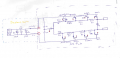
I have a circuit schematic for measuring leakage current using a current transformer (CT). I'm trying to understand how it works, but there are a few parts that don't quite make sense to me.
You can see the schematic in the attached image. In this schematic, T0 and T1 are the CT connection points.
I'm particularly trying to figure out the MOSFET structures used here. It seems like they were trying to make the burden resistor configurable (selectable). But since leakage current produces an AC signal, I'm not sure if the MOSFETs will work correctly under such conditions.
Do you also think this setup is intended to switch between different burden resistor values?
In my own design, I may also need to use 2 or 3 different burden resistor values, depending on the measurement range.
What would be a good way to implement that?
Attachments
-
 235.8 KB Views: 33


