I have a problem to implement a common source Cascode gain stage in the multistage amplifier design

Thread Starter

PorzDesign

Joined Jul 5, 2024
18
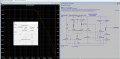
Greetings!!I did some tests and this is the best result I got... a bandwidth of around 42Khz (compared to the 5.2Khz I had previously with the same schematic but without the second current mirror(MOS M9 and I1)). I saw from the datasheet that the 2N7002 device appears to be in saturation for a VGs=5V and an ID=50mA therefore I opted for the solution in the schematic by creating an additional current mirror with an NMOS device(the mos M9). The only fact is that the open loop system is unstable since at unit gain the phase is approximately 209° (they are unstable for approximately 30° above)... If I introduce the miller capacitance to compensate the system the bandwidth is reduced and I know this... is there some additional technique that allows me to maintain a good bandwidth and maintain a decent phase margin ?? thank you very much!! Attached is the ltspice schematic(AMP_MULTISTAGE) and a screenshot of the test I had previously done with load resistor and nmos cascode bias with Vgs. I saw also that it is possible to implement a common source cascode stage to avoid the miller effect by trying to maintain a center band that has the differential output stage (it is around 1.2Mhz). The problem is that I can't implement a common source stage that gives me optimal gain and at the same time maintains a good center band.

I also tried the option in the photo(WITH BUFFER BETWEEN DIFFERENTIAL AND COMMON SOURCE STAGE) to try to isolate the common source with a buffer avoiding the Miller effect. in this way the common source gain is good (around 80db) and the center band of the differential is also maintained at the output. the only problem is that I also have instability here at open cycle of about 50° above the phase margin, and that's too much...


WITH BUFFER BETWEEN DIFFERENTIAL AND COMMON SOURCE STAGE.PNG
 

Attachments

Last edited by a moderator:

Thread Starter

PorzDesign

Joined Jul 5, 2024
18
thank you so much!!yes exactly,it is a project.I also saw that it is possible to fight the Miller effect with a transistor that internally implements a N mosfet si and a jfet sic. the problem is that I didn't find the ltspice model of this component..
 

MrAl

Joined Jun 17, 2014
13,680
thank you so much!!yes exactly,it is a project.I also saw that it is possible to fight the Miller effect with a transistor that internally implements a N mosfet si and a jfet sic. the problem is that I didn't find the ltspice model of this component..
Hi,

Maybe this is too new yet, but if there are devices out there already then they must have spice models for them.
If not you may be able to create your own based on the combination of an FET and a MOSFET. You'd have to accept that a real device would be slightly different, but then they all are anyway.

Did you by any chance mean to say the combination helps to mitigate the change in Rds with temperature?
 
Last edited:

Thread Starter

PorzDesign

Joined Jul 5, 2024
18
Hi,

Maybe this is too new yet, but if there are devices out there already then they must have spice models for them.
If not you may be able to create your own based on the combination of an FET and a MOSFET. You'd have to accept that a real device would be slightly different, but then they all are anyway.

Did you by any chance mean to say the combination helps to mitigate the change in Rds with temperature?
A thousand thanks!! the aim is to use real components and not monolithic MOSFETs that we size ourselves. I wanted to find a configuration for the common source stage that maintains the bandwidth of the differential stage and amplifies the signal. I tried with some configurations that I know, but I have always encountered problems in particular regarding the stability of the system beyond the permitted phase margin. if I go to use the Miller capacity I go to cut the bandwidth again. in short there are many compromises and maybe I thought that there is some configuration that maintains decent performance while satisfying both bandwidth, gain and phase margin.I thought about using to use the common source cascode configuration to widen the band and isolate the Miller effect from the differential stage, because it doesn't make sense that I have a bandwidth that presents the differential stage at the output of about 1Mhz and when I go to add a new one common source stage to amplify the signal it is drastically reduced to around 40Khz keeping the system unstable.
yes I also saw that it is possible to create a unique transistor with a nmos si and a jfer Sic to compensate for the Miller effect (Miller plateau), but I did not find these types of models on Ltspice
 

DickCappels

Joined Aug 21, 2008
10,661
I do not see any common gate transistor necessary to make this a cascode. You should try to concentrate mid (edit : most) of your gain in a single stage and apply your frequency compensation to that stage.

What type of signal do you want to amplify?
 
Last edited:

Thread Starter

PorzDesign

Joined Jul 5, 2024
18
I do not see any common gate transistor necessary to make this a cascode. You should try to concentrate mid of your gain in a single stage and apply your frequency compensation t that stage.

What type of signal do you want to amplify?
thank you!! A sinusoidal signal of +-10mV with a freq of 1kHz. I also checked the input dynamics to keep all the devices in the saturation region and I saw that VCMmax=3.71V and VCMmin=-1.46V
 

Thread Starter

PorzDesign

Joined Jul 5, 2024
18
Why have you used a common drain stage for M9? It would limit the output voltage to the drain voltage of M1.
Thank you very much!! To adapt the impedance and maintain the output bandwidth from the differential stage since the input common source stage presented me with a high capacity and therefore introduced a dominant pole which ruins the bandwidth. I thought about this but the system is unstable even if gain and bandwidth are kept high enough.
 

Ian0

Joined Aug 7, 2020
13,112
Almost every audio amplifier is designed with a common-source or common-emitter voltage-amplifier stage (see this from Douglas Self).
If you have more than two stages, each contributes a phase shift of 90°, so feedback around any more than two stages will almost certainly oscillate without a dominant pole capacitor.
74ED2149-9179-4BBF-8229-08F1371DEC15.jpeg
 

Thread Starter

PorzDesign

Joined Jul 5, 2024
18
Dealing with a low level 1 kHz sine wave, it seems unlikely that a cascode stage would be needed.

Keep it simple and you should see success more quickly.
I use the cascode configuration to limit the Miller effect(this devices they have high input capacities being power MOSFETs around 50pF for 2N7002 and 73pF for BSS84 for a 1Mhz frequency) and reduce the band that the differential stage presents to me at the output .In this common source cascode configuration with Wilson current mirror the differential band is maintained and I also have stability. The gain is missing though... I tried to add another common source stage to amplify the signal but it doesn't work
 

Attachments

Ian0

Joined Aug 7, 2020
13,112
Thanks!!But from the graph the center band width is minimal (tens of Hz),and the blue gain graph never crosses zero, so there is no unity gain at 0db, how do I determine GBW this way?
Choose any gain you like, multiply by the bandwidth at that gain. Provided that you are on the phase=90° part of the curve every choice of gain should give the same answer.
 

Thread Starter

PorzDesign

Joined Jul 5, 2024
18
Choose any gain you like, multiply by the bandwidth at that gain. Provided that you are on the phase=90° part of the curve every choice of gain should give the same answer.
I perhaps understood the trend of the curve. for such a small tail current of 1mA the differential pair does not work in saturation. From the datasheet the 2N7002 MOS require a maximum continuous drain current of 115mA. In fact in my scheme I have polarized them at 50mA per branch with a current mirror that generates 100mA
 

Ian0

Joined Aug 7, 2020
13,112
I perhaps understood the trend of the curve. for such a small tail current of 1mA the differential pair does not work in saturation. From the datasheet the 2N7002 MOS require a maximum continuous drain current of 115mA. In fact in my scheme I have polarized them at 50mA per branch with a current mirror that generates 100mA
A typical tail current for a long-tailed pair input stage would be between 100uA and 1mA. A long-tailed pair does not work in saturation.
A 2N7002 is capable of dissipating about 250mW, so any more than 2.5V across it at 100mA would kill it.
 

Thread Starter

PorzDesign

Joined Jul 5, 2024
18
A typical tail current for a long-tailed pair input stage would be between 100uA and 1mA. A long-tailed pair does not work in saturation.
A 2N7002 is capable of dissipating about 250mW, so any more than 2.5V across it at 100mA would kill it.
oh thanks.. on the datasheet I didn't find the max power it can dissipate.. but I'm seeing that for the on characteristic it also offers me a Vgs=10v with an Id=500mA for Id continuous ad Vgs=5V with an Id=50mA for Id pulsed.but then if I bias too low the band will be really small
 

Attachments

Ian0

Joined Aug 7, 2020
13,112
oh thanks.. on the datasheet I didn't find the max power it can dissipate.. but I'm seeing that for the on characteristic it also offers me a Vgs=10v with an Id=500mA for Id continuous ad Vgs=5V with an Id=50mA for Id pulsed.but then if I bias too low the band will be really small
How much gain do you need at 1kHz? What is your input signal level? MOSFETs are not the quietest of devices for small signal amplification. If you signal is really small, then bipolars would do a better job for a low impedance source and JFETs for a high impedance source.
 

Thread Starter

PorzDesign

Joined Jul 5, 2024
18
How much gain do you need at 1kHz? What is your input signal level? MOSFETs are not the quietest of devices for small signal amplification. If you signal is really small, then bipolars would do a better job for a low impedance source and JFETs for a high impedance source.
I would like to make a device that respects the typical performance of a multistage amplifier (amplification of a small differential signal, a gain of around 80/100dB, a bandwidth in the order of tens of KHz, phase margin respected...)
 
Top