Help Drawing Circuit for Problem.

Thread Starter

JimAnvil1234

Joined Apr 14, 2026
1
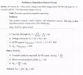
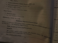
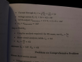
Hi all, I am currently studying to take the FE exam. I have attached photos of an FE study exam text book question. I have moved on but it's bothering me not to know, could someone please draw me the circuit the textbook is going for based on the problem and solution. I cannot for the life of me get a circuit that I work through that gets me to their solution. It is problem 9 from "FE Electrical and Computer Exam Prep 2026/2027" by Brady Elwood:

Problem 9 page 1 of 2.
AAC Problem 9.JPG

Page 2 of 2, up until problem 10.
AAC Problem 9 part B.JPG
 

Attachments

WBahn

Joined Mar 31, 2012
32,745
That is an EXTREMELY poorly constructed problem. Just HORRIBLE!

It doesn't indicate how the [series of 12 V and R1] is connected to [series of VCVS and R2].

It doesn't say what the polarity of the controlling voltage across R1 is.

It doesn't indicate what points the Thevenin equivalent is to represent.

It doesn't indicate if one of the components is to be considered the load.

Then, their solution fails to track units properly (sadly, way too common).

Then, their solution just makes it nonsensical.

They claim that the current in R1 is given by dividing the 12 V source by the sum of R1 and R2.

But this requires that R1 and R2 be in series AND that they be connected DIRECTLY across the 12 V source. But the problem precludes this because it explicitly states that the VCVS in series with R2, which means that the only way that 12 V can appear across R1 + R2 is if the output of the VCVS is identically zero. But that requires that the current through R1 be identically zero.

It is so self-contradictory that there is no circuit that satisfies it. I'd recommend throwing that exam prep guide away and getting a better one.
 

WBahn

Joined Mar 31, 2012
32,745
This is the LTspice operating point sim of my take on the circuit, but, as noted, the VCVS polarity is ambiguous:

View attachment 365982
That's the first thing that popped into my mind, but I don't see how it can be reconciled with their solution.

What would be your take on where the Vth port is for the circuit? Their claim is that when that port is open circuited, that R1 and R2 become effectively in series with V1. They also claim that Vth is equal to the output of the VCVS, which they further claim is 16 V when the Thevenin equivalent circuit is open circuited. But this contradicts the notion that 12 V appears across R1+R2 under these conditions.
 

MrAl

Joined Jun 17, 2014
13,677
Hello there,

[EDIT NOTE: The statement they gave that Vth=VCVS does not necessarily mean that the output is across VCVS, it can just mean that the two voltages are the same value]

Yeah this is kind of crazy. It reminds me of one of those programs you try to make as convoluted as possible just for the sake of seeing how convoluted you can get it to be.
It's like solving a circuit AND a real world logic problem at the same time (Bob did this, Alice did that, what color coat was Bob wearing).

I think we can follow the logic of the problem through by writing down all the facts and deducing the circuit(s) that results, but it just seems kind of stupid to have to do that. I would be different if it said, "Now try to draw the schematic of this circuit from the information given" because then it would make sense that they want you to have to figure out what the actual circuit looks like.

There seems to be a very direct problem that comes out though. If you want to read this read through it very briefly or skip to the end of this post at #14.

If we list the facts:
1. The 12v source is in series with R1=4 Ohms.
2. The VCVS is in series with R2=2 Ohms, and has a gain of 2.
3. The dependent source will stay active.
4. Current through R1=2 amps.
5. Voltage across R1=8 volts.
6. The VCVS output is 16v and it is the same as Vth.
7. Short circuit current iCS is 4 amps.
8. Rth=Vth/iCS
9. Rth=4 Ohms.

and then the implications:
10. Since the 12v source is in series with R1, it is most likely in series with something else. Usually if R1 is across 12v we would say "in parallel".
11. Since the VCVS is in series with R2, it is most likely in series with something else also. Same reasoning as R1 and 12v.

and then the combined implications of that:
12. Since in 10 the 12v is in series with R1 and in series with something else. the only thing left is the VCVS and R2 series combination. That puts all four in series. The question is, does this give us the correct results after we try to find a connection for the sense input of the VCVS.

13. We can deduce that the sense input of the VCVS is V1 which is the voltage across R1, so there are only two possibilities for the connections of the positive and negative sense leads.

14. Doing all of that, since in #6 the VCVS is the same as Vth, then to get the short circuit current we have to short out that source, which means its voltage goes to zero even if its current does not.
When we do that, we end up with R1 and R2 in series across the 12v source, which only gives us 12/6=2 amps, and it does not matter where or how we connect the sense leads of the VCVS or what polarity the source terminals takes on. Once it is shorted, it's zero volts.

Presently I don't see any way we can get a short circuit current of 4 amps. Once the VCVS voltage is zero, the current through the shorting wire can only be one of:
A. 12/(4+2)
B. 12/4
C. 12/2
D. 12/(2||4)
None of these leads to a current of 4 amps. We do get 2 amps, 3 amps, 6 amps, and 9 amps.

Maybe this is one of those "Do as I say, not as I do" problems (ha ha).
Maybe this is a topology switched network where we have to switch between two or more topologies and use the average short circuit current. If we switch between the 2 amp solution and 6 amp solution at 50 percent duty cycle we get an average of 4 amps :)

There are other deductions we could make too though, but anybody see anything different?
 
Last edited:

WBahn

Joined Mar 31, 2012
32,745
If "Isc" (short circuit current) is interpreted as a "given" value, then:

View attachment 365986
Except the description states that the VCVS is in series with R2 I'm also not following what your additional voltage source and resistance, which are clearly not mentioned in the problem statement, are doing.

Is your circuit port between Node th and GND? If so, the while the open-circuit voltage is 16 V, the short-circuit current would be infinite since you are short-circuiting the VCVS.
 

MrAl

Joined Jun 17, 2014
13,677
Hello again,

It is starting to look like there is no consistent schematic with solution that satisfies all of the statements given in the original text.
We can keep looking I guess, but in the meantime here is a cleaned-up version of the original two texts. This should be much easier to work with anyway.
 

Attachments

eetech00

Joined Jun 8, 2013
4,704
Except the description states that the VCVS is in series with R2 I'm also not following what your additional voltage source and resistance, which are clearly not mentioned in the problem statement, are doing.

Is your circuit port between Node th and GND? If so, the while the open-circuit voltage is 16 V, the short-circuit current would be infinite since you are short-circuiting the VCVS.
The problem description is a matter of interpretation. I believe the problem has been purposely written to mislead (as are many exams questions of this type). I don't believe there meant to be a literal 0 ohm short circuit of the VCVS output.

But what I've shown is a circuit drawing that fits the "solutions" math (which is what the TS asked).
 

WBahn

Joined Mar 31, 2012
32,745
The problem description is a matter of interpretation. I believe the problem has been purposely written to mislead (as are many exams questions of this type). I don't believe there meant to be a literal 0 ohm short circuit of the VCVS output.

But what I've shown is a circuit drawing that fits the "solutions" math (which is what the TS asked).
So draw your circuit in a box that has two terminals on it.

To the outside world, does that box behave, at those terminal, like a 16 V source in series with a 4 Ω resistor?

Keep in mind that this is NOT a question on the FE exam, it is a question from some study guide that someone has published claiming to help prepare people to take the FE exam. My experience, albeit it several decades in the past, was the FE exam was extremely well written with virtually no tricky questions. When I took it (and it has changed quite a bit since then), the exam was nine hours (two parts with a break in between) and consisted of 140 questions the covered Math/Computers, Materials/Physics, Chemistry, Economic, Electrical Theory, Thermodynamics, Statics, Dynamics, Mechanics of Materials, and Fluid Mechanics (I'm not dredging that up from memory, I still have my FE Exam Guide from when I took it). Everyone took the same exam, whether you were a civil engineer, an electrical engineer, a chemical engineer.

So the exam was structured with the recognition that most people would be very weak in a few areas and very strong in others -- the goal was to evaluate whether the person had sufficient foundational knowledge, in both breadth and depth, to begin working as an EIT (Engineer in Training) on a multi-year path that would, hopefully, lead to licensure as a PE (Professional Engineer). To me, most of the questions that were in a person's field of study could be answered almost by inspection by quickly estimating bounds on the answer and eliminating the obviously wrong choices, which often only left a single answer available. The other questions were generally answerable in a reasonable amount of time if you had a firm grasp of mostly sophmore-level topics in that field. I have no idea how the scores on the ten topic areas were combined into a total score or what the minimum passing score was -- they only give you a pass/fail result. It used to be done on one specific day (in an area) and at the testing center I went to (a exhibition hall in the Denver area) there were hundreds of people taking it. At my table there were three others and two of them had failed it twice already. The other guy and I were first-timers.

Today is it a six hour exam session and you take a topic-specific exam electronically at a testing center that is scheduled on a individual basis. Personally, I would rather see it remain broadly based topic wise. Also, there's something to be said about the experience of taking a significant step from academia to the real world by doing it en mass with others that are sharing the same experience at the same time. But perhaps that's just nostalgia talking.

Here's some questions I've found in current online practice exam sites. Since I'm not willing to pay for them, I can only see the handful of questions they make visible as a teaser.

1776298423152.png
1776298348616.png
1776298602685.png
1776298699260.png

The last one is a prime example of what I was talking about. By inspection, you can eliminate the first two answers immediately since the circuit starts with 6 Ω of series resistance. This is in series with the parallel combination of 6 Ω (two 12 Ω resistors in parallel) and 12 Ω (two 6 Ω resistors in series), which you know must be less than 6 Ω so the total resistance has to be less than 12 Ω, making it clearly closer to 10 Ω than to 15 Ω, so there is only one possible answer. Pick it and move on.
 
Last edited:

MrAl

Joined Jun 17, 2014
13,677
The problem description is a matter of interpretation. I believe the problem has been purposely written to mislead (as are many exams questions of this type). I don't believe there meant to be a literal 0 ohm short circuit of the VCVS output.

But what I've shown is a circuit drawing that fits the "solutions" math (which is what the TS asked).
Hi,

I also misinterpreted the text at first. I originally thought that if they said Vth=VCVS that meant that VCVS was the output of the circuit. That would only be if physically Vth was taken to be across the output of the VCVS, but if we interpret this more correctly (I believe) then they just meant that:
"The voltage of Vth is equal to the voltage of the VCVS"
So if VCVS=2v then Vth=2v, but they do not have to be in the same place in the circuit. Vth could be two completely different nodes apart from the two nodes of the output of the VCVS, or they could have one node in common. Unfortunately, that also leaves us with the task of finding out what two nodes we use as the Vth output and that means what we actually have to short out to find the short circuit current.

We could prove or disprove this definitively by using trial and error combinations for all the circuit elements. To match the descriptions though, I think we can cut the search field down to just two elements:
1. The 12v in series with R1.
2. The VCVS in series with R2.

but then we still need to find out what two nodes to take Vth from.

So to start, how many combinations of #1 and #2 could there possibly be, before we try to figure out where to take Vth from.
To start the list we can refer to these as x1 and x2. Then we have, to start:
x1 in series with x2
x1 in parallel with x2
x1 in parallel with VCVS
x1 in parallel with R2
x2 in parallel with 12v
x2 in parallel with R1
There could be other combinations like x2 from the junction of 12v and R1 to ground. Some of these may prove bad right off.
If we go through each combination, then we have some alternatives for where we take Vth from:
across x1
across x2
across 12v
across R1
across VCVS
across R2
Are there any other possibilities.

Once we go through every combination and every possibly output for Vth, if we never find a version that matches all the lines of text in the description, we prove that the circuit is impossible.
Some versions may cancel right away, like taking the output for Vth from across VCVS. That does not seem to work at all as I discovered, but I did not try every combination yet.

ac
 

MrAl

Joined Jun 17, 2014
13,677
Hello again,

Oh, I think I found a solution, but to get it we have to swap R1 and R2 values. That means R1=2 and R2=4 Ohms.
Maybe that means they mixed up the values of R1 and R2.

I have to check this out more carefully though...

A simpler example is to just add a third resistor R3 on the output of the VCVS, then we get 16v, 4 amps, and Rth is 4 Ohms.
12v in parallel with (2 Ohms in series with 4 Ohms = 6 Ohms total), take the sense across the 4 Ohms, gain A=2.
 
Last edited:

WBahn

Joined Mar 31, 2012
32,745
Let's keep in mind that this is supposed to be an example of a problem that the person could see on the FE exam, which currently consists of 110 questions in 5 hours and 20 minutes, which means that they have less than three minutes per question, on average. Of course, some questions are a lot quicker than others, but if they even ten minutes each on just few questions, they start seriously crowding their time on the rest of the exam. Also, they only have the question, so they can't play the game of figuring out what circuit configuration matches answer. And the notion of adding additional components to get the right answer is unreasonable on many fronts. If I'm free to do that, I can easily get any answer I want by just putting a source of Vth in series with a resistance of Rth as by equivalent and then connect them at a single point to whatever circuit components I think they are describing. But not only does that totally defeat the point, I can't do that unless I know what values of Vth and Rth I'm supposed to end up with.

I think the fact that the author felt it worthwhile to make the statement, "Complex analysis required," is a likely indicator of the author's proficiency in fundamental circuit analysis.
 

MrAl

Joined Jun 17, 2014
13,677
Let's keep in mind that this is supposed to be an example of a problem that the person could see on the FE exam, which currently consists of 110 questions in 5 hours and 20 minutes, which means that they have less than three minutes per question, on average. Of course, some questions are a lot quicker than others, but if they even ten minutes each on just few questions, they start seriously crowding their time on the rest of the exam. Also, they only have the question, so they can't play the game of figuring out what circuit configuration matches answer. And the notion of adding additional components to get the right answer is unreasonable on many fronts. If I'm free to do that, I can easily get any answer I want by just putting a source of Vth in series with a resistance of Rth as by equivalent and then connect them at a single point to whatever circuit components I think they are describing. But not only does that totally defeat the point, I can't do that unless I know what values of Vth and Rth I'm supposed to end up with.

I think the fact that the author felt it worthwhile to make the statement, "Complex analysis required," is a likely indicator of the author's proficiency in fundamental circuit analysis.
Hi,

Sure, but since we could not find a solution we started to think about the simplest addtions or changes that would make it work. I first thought about swapping R1 and R2, but now I don't think that works either. There are more constraints than there are variables. Introducing one more variable seems to solve it, although that may come in different ways.

That's funny that you mentioned the authors use of the phrase "complex analysis required" and seem to take that as meaning they sort of knew what they were doing.
I take that to be just the opposite, because when we say "complex analysis" in circuit analysis we usually mean we have to use complex number math. A better choice would have been "complicated analysis" I think. That tells me that the proficiency is less than we would like to see. Combine that with the fact that nobody can find a solution and we have the answer I think. It's a mock version of a problem not a real circuit problem.

I sort of stopped looking for solutions anyway because it's too much time for such a silly idea. That, and it was not part of the problem question anyway I don't think it was just a curiosity for the student. Maybe that should tell us what we should really do and not do.
 

WBahn

Joined Mar 31, 2012
32,745
Hi,

Sure, but since we could not find a solution we started to think about the simplest addtions or changes that would make it work. I first thought about swapping R1 and R2, but now I don't think that works either. There are more constraints than there are variables. Introducing one more variable seems to solve it, although that may come in different ways.

That's funny that you mentioned the authors use of the phrase "complex analysis required" and seem to take that as meaning they sort of knew what they were doing.
No, I side that it is a likely indicator of the author's proficiency in fundamental circuit analysis. I never said that it indicated that said proficiency was very high. The fact that my very first response stated with, "That is an EXTREMELY poorly constructed problem. Just HORRIBLE!", followed by multiple points of glaring deficiencies in its description, should be a pretty good indicator of my opinion of their proficiency.
 
Top