 Facebook
 Google
 GitHub
 Linkedin
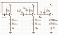
Well not so much of a problem but what i am trying to do is have a little filter fun, i have posted the circuit i am playing with, it is the filter section from a colour organ i found online consisting of 3 channels (filters) bass, middle and treble, i have only built the middle filter and replaced R8 with a 10K pot set to around 5K, the circuit works, as i turn the pot the output varies as the filter changes which is what i wanted but why do i only have the top half of the waveform appearing at the output?
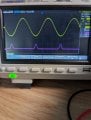
My input signal into R7 is 1kHz at 1.75V AC coupled and is seen in the yellow trace, my output is the purple trace.
I have got so far and now i'm stuck, i was expecting the full sinewave on the output, the collector of Q3
My input signal into R7 is 1kHz at 1.75V AC coupled and is seen in the yellow trace, my output is the purple trace.
I have got so far and now i'm stuck, i was expecting the full sinewave on the output, the collector of Q3
Attachments
-
 228.2 KB Views: 31
 -
 2.2 MB Views: 29


