 Facebook
 Google
 GitHub
 Linkedin
Hello everyone. I have a problem regarding low pass pi filters. For context, I am a physics student and this is way, and I mean WAY outside of my purview. So much so, that I can't find this circuit, or anything like it in my textbooks. After some gruesome research, I found some formulas which I honestly can't explain, I have no idea where they come from, or if they are correct. My solution uses transfer functions which we haven't covered, but I truly can't think of anything else which accounts for voltage amplitudes.
So, the setup is the following:
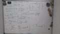
Amplitude of U_out is 10 times smaller than the amplitude of U_in. [Sorry if that's not correct in the electronic lingo, English is not my first language]. If the capacitance is 10 micro-Farad, and the frequency is 100 Hz, find the inductance L.
In the picture below is my work, I would be grateful if someone could check it for me.
As you can see, I got ~L=2.5H, which seems a bit high, given that in the lab, we've only worked with mili, or even micro Henries. Also, this doesn't account for 2 capacitors, instead only using one of them, instead of parallel connection or something. I really don't know.
So, the setup is the following:
Amplitude of U_out is 10 times smaller than the amplitude of U_in. [Sorry if that's not correct in the electronic lingo, English is not my first language]. If the capacitance is 10 micro-Farad, and the frequency is 100 Hz, find the inductance L.
In the picture below is my work, I would be grateful if someone could check it for me.
As you can see, I got ~L=2.5H, which seems a bit high, given that in the lab, we've only worked with mili, or even micro Henries. Also, this doesn't account for 2 capacitors, instead only using one of them, instead of parallel connection or something. I really don't know.
Attachments
-
 125.3 KB Views: 24


")


