MOSFET Drain current measurement is my logic current

Thread Starter

hoyyoth

Joined Mar 21, 2020
528
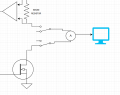
I have a test system which consists of 12 mosfets and I need to measure and log the drain current flowing through these mosfets in a manner such that first I will measure from 1st mosfet turn it off then measure from second mosfet and so on.

Only one ammeter is used(DMM as ammeter) .

I will use two spdt relays .Initially the ammeter is connected to NC pin of the SPDT relay and it is floating.
During measurements relay is activated and ammeter is connected to NO pin of both relays.
May I know is this logic correct .Can I implement this with one realy.

1743432073773.png
 

Attachments

Janis59

Joined Aug 21, 2017
1,894
FET gate current in the DC regime is definitely equal to zero. You have nothing to measure. Only the current one be able to measure is high frequency obstacles, and ammeter in such case is all ever worst nightmare instrument. Ought to use the oscilloscope and one ohm resistor or 3...5...10 Ohms depending on power) in series.
 

Thread Starter

hoyyoth

Joined Mar 21, 2020
528
1743443445545.png
Two SPDT relays are used as shown in the figure.

Gate and drain are powered from different power supplies.

Maximum drain current is 32A
 

Thread Starter

hoyyoth

Joined Mar 21, 2020
528
FET gate current in the DC regime is definitely equal to zero. You have nothing to measure. Only the current one be able to measure is high frequency obstacles, and ammeter in such case is all ever worst nightmare instrument. Ought to use the oscilloscope and one ohm resistor or 3...5...10 Ohms depending on power) in series.
The maximum drain current is 32A.
 

Irving

Joined Jan 30, 2016
4,996
I have used two spdt relays.
But why? This is a very poor way to measure drain current as very few cheap relay contacts will reliably switch 32A for very many cycles. Measuring the voltage drop across the sense resistor will be both more accurate, faster and less prone to error or failure.
 

Thread Starter

hoyyoth

Joined Mar 21, 2020
528
But why? This is a very poor way to measure drain current as very few cheap relay contacts will reliably switch 32A for very many cycles. Measuring the voltage drop across the sense resistor will be both more accurate, faster and less prone to error or failure.
Yes you are correct sense resistor is accurate.
We need to characterize the mosfet.
The drain current is measured for days.This data needs to be logged into a PC.
I don't know whether current measured my ADC(sesnse resistor method) we will be able to log to PC and save.
If I use a digital multimeter it has USB interface and with the help of Pyvisa I can save the data to PC
 

Irving

Joined Jan 30, 2016
4,996
Of course you can log it to the PC via USB, serial UART or WiFi. That's a trivial piece of programming these days. Though at 32A I'd probably not use a sense resistor but a Hall effect sensor as it requires much less hardware and has less drift due to heating - a standard 50A shunt (1.5mOhm) will dissipate nearly 1.5W with an output voltage of 48mV, whereas a 50A Hall sensor is 1/15 the resistance value and will give around 1.6v needing little or no signal processing.
 

Thread Starter

hoyyoth

Joined Mar 21, 2020
528
Of course you can log it to the PC via USB, serial UART or WiFi. That's a trivial piece of programming these days. Though at 32A I'd probably not use a sense resistor but a Hall effect sensor as it requires much less hardware and has less drift due to heating - a standard 50A shunt (1.5mOhm) will dissipate nearly 1.5W with an output voltage of 48mV, whereas a 50A Hall sensor is 1/15 the resistance value and will give around 1.6v needing little or no signal processing.
Thank you very much.This is very informative.I never worked with hall sensors.If you don't mind can you suggest a hall sensor for this application.So that I can start learning from there.
 
Top