555 voltage booster

Papabravo

Joined Feb 24, 2006
22,082
The tripler looks like the first three diodes worth of the circuit in post #55, with the common being the same as shown, and the output being at the top of D3. I will need to check my reference books for the tripler, never used one yet. The voltage rating of the capacitors varies with their position in the circuit.
Note that an actual tripler must have at least three capacitors and at least three diodes.
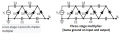
There are losses to account for in the CW circuit, that is why my simulation has four(4) stages. The DC output at 31.9V is a bit more than 3 times the peak output from the transformer secondary. Although not absolutely necessary to the operation of the circuit, The transformer would provide isolation if the voltages were higher. Also I did not bother putting a load resistor on the output because I already know what would happen. This circuit is not likely to be suitable for the stated purpose of the TS.

A boost ratio of 3:1 is reasonable for an unregulated SMPS circuit, with the same restriction that the power out will be less than the power in.
 

Papabravo

Joined Feb 24, 2006
22,082
I kind of understood the point about the parts count, I'm just looking for a tripler that maintains the ground at the output so I can create the plus and minus voltages. Good for opamps don't you know.
There is nothing wrong or irregular with "the ground at the output". Why do you think there is? All the voltage nodes in the circuit are measured with respect to the same common ground. WTF do you not understand?
 
Last edited:

Thread Starter

Wendy

Joined Mar 24, 2008
23,798
This schematics you keep showing me do not show the output tied to the the ground, I dislike making assumptions. And prefer not to. WTF, why is that so hard to understand?
 

Papabravo

Joined Feb 24, 2006
22,082
I don't know what you mean by "tied to ground". I'm asking you to tell my why you think the net name "+31.9V" is anything other than a net with respect to ground which is the triangle symbol connected to the transformer secondary.

EDIT: Would you be happy if I included a very large resistor to ground from the net "+31.9V"? Seriously you need "training wheels" to correctly understand a circuit.
 

MisterBill2

Joined Jan 23, 2018
27,528
OK, the circuit does not show the input or output tied to "ground" because there is no reason to tie them to it. BUT following the line from the input low side it is simple to trace it to the output low side. So what you have IS OUTPUT RETURN COMMON WITH INPUT RETURN. And as that equates to what was asked for, it should be good. A connection to ground does do much for you at all. But the low side can be tied to "ground", or the power source common.
 
Last edited:

MisterBill2

Joined Jan 23, 2018
27,528
The voltage multiplier in my reference book is the same C.W. multiplier but it looks very different when it is drawn functionally, which is with two strings of capacitors and the diodes all at angles, all in series.
Drawing the circuit with all of those ground symbols confuses the issue and is incorrect, besides. And the 100G resistor between two grounds is a waste of resources.
 

Thread Starter

Wendy

Joined Mar 24, 2008
23,798
So, would this be a voltage tripler?
00.png

again I know it would be less than three times whatever the supply voltage would be, but it would give me something to start with.
 

Papabravo

Joined Feb 24, 2006
22,082
The voltage multiplier in my reference book is the same C.W. multiplier but it looks very different when it is drawn functionally, which is with two strings of capacitors and the diodes all at angles, all in series.
Drawing the circuit with all of those ground symbols confuses the issue and is incorrect, besides. And the 100G resistor between two grounds is a waste of resources.
The large resistor is not really a "resource" per se, it is a simulation representation of a large impedance between primary ground and secondary ground.
 
Last edited:

MisterBill2

Joined Jan 23, 2018
27,528
OK, I found some other, different, tripler and quadrupler circuits. They are published in the older "Radio Amateur's Handbook", in the power supply chapters, towards the end of the section. Both in the 1966 handbook and in the 1976 handbook. Could not find them in the newer issues of the handbook. And the circuits do have the input and output negatives common to each other.
 

Thread Starter

Wendy

Joined Mar 24, 2008
23,798
The brain fog and lack of notebook is really eating my lunch, the second figure is my attempt to redraw the first:
Vmultiplier.png

00.png
would someone please proof the schematics please?
 
Top