555 voltage booster

Thread Starter

Wendy

Joined Mar 24, 2008
23,421
I am doing something unusual for me this time In this thread in that I will be doing experiments very close to real time and publishing the results as I get them.

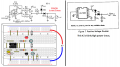
I have had an idea for a while that involves boosting the output of a CMOS 555,The first thing I had to do was verify that the CMOS 555 could provide 1ma source/sink in. Shoot through is definitely going to be a problem with this design I am hoping to minimize it from the 555 fast transition times. If I am wrong I will work on other solutions in future revisions.


Voltage booster #1a.png

!b.png
 
Last edited:

MrSalts

Joined Apr 2, 2020
2,767
Why is the 555 output connected to the timing RC network? Is this a flipflop or other non-standard use? Any monostable or astable can be POWER BOOSTED with the circuit shown in Post #2.

Your schematics in POST 1 are showing the same Vcc supplying the 555 and the transistors so I am not sure how you expect to get a VOLTAGE BOOST as defined in your title.

You'll have to clarify your goal because 555 timers are rail to rail output so I don't understand the need for a voltage boost unless you are talking about a second (higher) power rail that is yet to be defined.
 

Thread Starter

Wendy

Joined Mar 24, 2008
23,421
1. I want rail to rail.
2. The transistor configuration is inverting. A hysteretic oscillator requires an inverting Schmitt trigger to work. two inverting gates is a buffer.
3. A CMOS 555 at low voltage has a very low drive, I wasn't sure it could handle 1ma at 5V Vcc.The transistors will raise that considerably.
 
Last edited:

crutschow

Joined Mar 14, 2008
34,409
Below is the LTspice simulation of your second circuit.
As you can see, there are significant current spikes during the signal transition, as well as current through the transistors when high, since the 555 only goes to about 1.5V below the supply voltage.

1653144112751.png
 

Audioguru again

Joined Oct 21, 2019
6,688
A 555CN is an ordinary old TTL 555. It already produces 400mA of shoot-through current.

A Cmos 555 is a LMC555, TLC555 or ICM7555.
The datasheet for the ICM7555 has graphs showing "typical" voltage loss vs output current. Some are better, others are worse.
A Cmos 74HC Schmitt Trigger logic IC produces much more output current.
 

Attachments

Thread Starter

Wendy

Joined Mar 24, 2008
23,421
The 555 will start high, then as the oscillation progresses ( the capacitor charges) goes low.

My next experiment...

Voltage booster #2a.png

My goal is to produce 9V from 5V then I may try for +/- using a similar approach for op amps. I picked 20Khz because (except for a few rare individuals it is beyond human hearing. I'm not sure of the diode orientation, I shall see. The reactance of the caps is less than 1Ω.
 

Thread Starter

Wendy

Joined Mar 24, 2008
23,421
Where do people go to sell obsolete things? Why Amazon, of course. i don't care, i like old stuff. i miss my old C64.
 
Last edited:

Thread Starter

Wendy

Joined Mar 24, 2008
23,421
So I tested this today, and was quite surprised to find I got 10 volts out. I loaded it down with a potentiometer, until I got 9 volts. The resistance was 3KΩ.

Voltage booster #2a.png

There was almost zero ripple that I could measure. Now to expand on this theme.​
 

MisterBill2

Joined Jan 23, 2018
18,463
I think that there is a voltage tripler that has a common low side, input and output.

And if you really like old stuff, I have a 6502 Tandy color computer that you may be interested in. I have thought about trying a color computer as a CW send/receive encoder/decoder, adding an attached LCD screen. The program prom would live inside and fold up above, The benefit is that it would serve as a single function device with stuff inside actually serviceable without a microscope.And running a program from ROM it would be ready in just a few seconds from power on.
 

Thread Starter

Wendy

Joined Mar 24, 2008
23,421
No thanks, if I want my 6502 fix I have a C64 emulator in in my library. If I had the room I probably still have my C128 setup. As is I will spend a few more days on this project trying to see if I can understand how to up the current output. As is I'm pretty sure I can come up with a ±10 volts which would handle a lot of op amp audio projects.
 
Top