40 LED Cascaded Decade Counter

Thread Starter

Brotron

Joined Aug 8, 2024
27
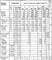
You still don't have the datasheet to hand????

Here you go:

/QUOTE]
Appreciate it, I have it now and its a bit different from yours, still on the high side for the chip but not quite as drastic. looks like it will take about 3mA with a 15 Volt supply at around 70 degrees. I had looked at this initially and since I'm making this circuit from a working design I found online, I guess I figured it would be fine. Most of my assumptions about these numbers are guesses anyway. Its the downside of teaching yourself electronics by reverse engineering circuits from unverifiable sources:)
 

Attachments

Thread Starter

Brotron

Joined Aug 8, 2024
27
You are using Q0 to cascade your CD4017 counters?
You should be using CARRY OUT instead.
That would make more sense to me also, I based my circuit from an online source that I thought was valid. I'm going back to bread board and will try pin 12 for the cascade. Thanks
 

Thread Starter

Brotron

Joined Aug 8, 2024
27
I'm glad you called it a wiring diagram (and a very colorful one at that) and not a schematic.
Sorry, not the easiest thing to debug a circuit from... but from since my wiring is my noob translation of the schematic, I wanted to show how I had wired it and not how I should have wired it. This was the visual I guide I drew up as I tried to figure out what was wrong. The colors match the actual wires colors in my protoboard!
 

Thread Starter

Brotron

Joined Aug 8, 2024
27
In your second diagram you have your 104 caps in series with the positive power inputs...that's not correct, they should be across the power pins.

It also looks like the 10uf cap is connected wrong.
Would this address what is wrong or did I make it worse? I could have my anode and cathode mixed up in my 10uf, I'll know if the top pops off:) Thanks
 

Attachments

dl324

Joined Mar 30, 2015
18,341
The colors match the actual wires colors in my protoboard!
I tend to use brown wires these days (bought a couple 1000' spools on clearance at Circuit Specialists). Appropriate wire length is more important to me, but I'm not a believer in the flat wire method because I think it usually makes it more difficult to trace nets.
breadboardExample.jpg
The blue wire was because I was too lazy. This is several different circuits.
 

MrChips

Joined Oct 2, 2009
34,835
Sorry, not the easiest thing to debug a circuit from... but from since my wiring is my noob translation of the schematic, I wanted to show how I had wired it and not how I should have wired it. This was the visual I guide I drew up as I tried to figure out what was wrong. The colors match the actual wires colors in my protoboard!
And another thing. There is a difference between a wiring diagram and a circuit diagram.

It is nice that you showed your breadboard with wonderful colours that you choose. That’s a wiring diagram for someone who is doing the wiring and don’t give a hoot of how the circuit works. We don’t care what colours you choose as long as they make sense to you.

Circuit designers and engineers use circuit diagrams. We want to see connections drawn based on function, not based on chip layout.
 

Thread Starter

Brotron

Joined Aug 8, 2024
27
My colors were based on the repeatin
It is nice that you showed your breadboard with wonderful colours that you choose. That’s a wiring diagram for someone who is doing the wiring and don’t give a hoot of how the circuit works. We don’t care what colours you choose as long as they make sense to you.
My colors were based on the repeating pattern in the bundle of jump wires I bought. If I knew what I was doing there would be far less tracing wires back to the source to find out what went wrong. I promise, when I reach some level of mastery, it will no longer look like a unicorn threw up a rainbow on my protoboard!
 

ElectricSpidey

Joined Dec 2, 2017
3,335
Would this address what is wrong or did I make it worse? I could have my anode and cathode mixed up in my 10uf, I'll know if the top pops off:) Thanks
This is the correct electrical connections.

But the mechanical connections of the 104s should be as close to the power pins of the chips as possible.
 

AnalogKid

Joined Aug 1, 2013
12,145
You are using Q0 to cascade your CD4017 counters?
You should be using CARRY OUT instead.
Nope.

The intent of the TS is to extend the 4017 output pattern to more outputs, not cascade multiple counters.

The circuit shown in posts 24 and 30, and a circuit using the Carry Out, are two different circuits with different operating functions. The 24/30 circuit "expands" multiple 4017's so they act as a single counter with more outputs. The walking or shifting output pattern steps through all of the counters, with only one output on at a time, before starting over. Using the Carry Out, each counter cycles around itself, incrementing the next counter once for each complete cycle of ten clocks. In this case, multiple LEDs will be on at the same time. It is like a "normal" 2-digit counter, such as a totalizer: the tens digit increases once for every ten counts of the units digit. For the TS application, do not do this. Stick with the approach you have.

ak
 
Last edited:

eetech00

Joined Jun 8, 2013
4,707
I was trying to build an analog counter with chips I had on hand, and then it got out of hand. I breadboarded this circuit and it worked, I built a protoboard from it and it worked until I mounted it and then a section went dark. Now Ive rebuilt the board twice and I cant get it to work at all. Here is the wiring diagram, is there something inherently wrong with this circuit that would make the chips fail? Not shown in the diagram but all the LEDs were grounded with 200 ohms so they were receiving around 15 milliamps. Thanks for any help!
I didn't see in any post where you've written how you want the LEDs to light. Which pattern are you attempting to light the LEDs?
Did you want the 40 LEDs to light in sequence, one after another, with only one LED on at any time?
What about at power on? No LEDs should light? or?
 

Thread Starter

Brotron

Joined Aug 8, 2024
27
I didn't see in any post where you've written how you want the LEDs to light. Which pattern are you attempting to light the LEDs?
Did you want the 40 LEDs to light in sequence, one after another, with only one LED on at any time?
What about at power on? No LEDs should light? or?
Sorry for leaving out the backstory. Its a sequence of LEDs controlled by a toggle switch. The LEDs light up one at a time in order of 1 to 35 with each click of the switch and then cycle back to 1. They are light up numbers in a vintage looking dated mail cabinet. I could have gone with a microcontroller and synced to the actual date but I thought I would learn more doing it this way, which I have, and I had the decade counter chips from another project anyway.1725467795515.png1725468442151.png
This is a pic of the board that actually worked before I bent down all the wires to mount it. Maybe it was a fluke as I cant get the same design to work again. And I miss-read some of the resistor values, it had two 300 Ω in series after the LEDs not two 100 Ω , so I was only sending out around 5 mA to each LED.
 
Last edited:

eetech00

Joined Jun 8, 2013
4,707
Hi

I know you've already wired your design, but your diagram is difficult to analyze. The circuit below follows the method of cascading CD4017Bs for the sequencing of 1-35 Leds you want. Your project wiring connections should be the same.
Note that I have shown resistors in place of each led for proof of concept only. The CD4017Bs output pins cannot safely support 5mA output drive current using a 5v supply voltage, so there is risk of damage to the chips. You'll need to use a transistor driver connected to each output that then drives its LED. Also, you might need to provide a better switch debounce circuit if the switching sequence behaves erratically.

1725475210979.png

1725474811218.png
 

Thread Starter

Brotron

Joined Aug 8, 2024
27
What does it do now? I assumed you've already checked for broken connections.
It was lighting up one of the LEDs on the second 4017 and then jumping to the fourth 4017 so a section in the middle went dark. I checked all the connections and replaced the second chip but it was still doing the same thing so I think I may have damaged the and gates in the 4081B. At that point I just started over which is probably for the best now that I know I was pushing too much amperage through the 4017s.
 
Top