 Facebook
 Google
 GitHub
 Linkedin
Hi,
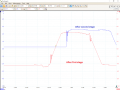
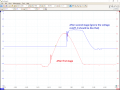
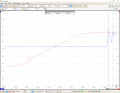
I am designing an analog circuit that resembles a Gaussian shaping amplifier (takes voltage spike looking signals at the input and integrates it to a Gaussian shape voltage signal preserving the amplitude with a particular ratio). I chose the cascaded 2 stage Sallen-Key filter topology for that. Unfortunately, I get quite nasty ringing of give or take 13 MHz in my signal that I can not eliminate on my own (my input signal is around 1 us, expected output signal is around 8-10 us, I use LT1365 opamps).
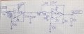
In general, the circuit works and does what is required from it. But I can not get rid of this 13 MHz oscillation. (It is acquired after first stage, the second stage only amplifies the oscillation a little bit more.) What's interesting that this tone is not applied to all the signal. I usually get just a few high amplitude oscillations on the rising edge, but after that 13 Mhz tone is not present in the signal any longer. This might be a pole of the opamp, but I am not sure, since the original signal frequency is not that high... I tried to put a series 5.1K resistor on the output of the second stage and measure the signal through it. Signal gets a little smother, but that 13 Mhz rising edge stuff is still strong. I also tried to put an additional opamp buffer at the output to load the second stage properly, but that did not make any difference. There's a circuit diagram in the attachments. The 47K series resistor in the second stage feedback path (feedback to the positive terminal of the opamp.) is added to eliminate another unwanted effect: before I have added that resistor, my opamp was introducing significant undershoot right before the rising edge of the signal. So I added the series 47k resistor in the feedback path experimentally, and solve that problem. Other than that, I guess it's just better for you to take a look at the circuit and ask for an additional clarification if needed.
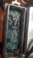
I have already made the PCB and yet made quite a few modifications to it (picture in the attachments). I did not preserve the factory look of the PCB, had to cut a few traces and solder some additional wires. In the end, it does not seem like I have introduced significant amount of parasitics to it, however I can guarantee, that I have strong decoupling for my opamps. I really need to make this board working one way or another, so changing the topology or redesigning a PCB is not useful suggestion in this case... I really appreciate any observations and help how should I solve this problem. Thanks.
I am designing an analog circuit that resembles a Gaussian shaping amplifier (takes voltage spike looking signals at the input and integrates it to a Gaussian shape voltage signal preserving the amplitude with a particular ratio). I chose the cascaded 2 stage Sallen-Key filter topology for that. Unfortunately, I get quite nasty ringing of give or take 13 MHz in my signal that I can not eliminate on my own (my input signal is around 1 us, expected output signal is around 8-10 us, I use LT1365 opamps).
In general, the circuit works and does what is required from it. But I can not get rid of this 13 MHz oscillation. (It is acquired after first stage, the second stage only amplifies the oscillation a little bit more.) What's interesting that this tone is not applied to all the signal. I usually get just a few high amplitude oscillations on the rising edge, but after that 13 Mhz tone is not present in the signal any longer. This might be a pole of the opamp, but I am not sure, since the original signal frequency is not that high... I tried to put a series 5.1K resistor on the output of the second stage and measure the signal through it. Signal gets a little smother, but that 13 Mhz rising edge stuff is still strong. I also tried to put an additional opamp buffer at the output to load the second stage properly, but that did not make any difference. There's a circuit diagram in the attachments. The 47K series resistor in the second stage feedback path (feedback to the positive terminal of the opamp.) is added to eliminate another unwanted effect: before I have added that resistor, my opamp was introducing significant undershoot right before the rising edge of the signal. So I added the series 47k resistor in the feedback path experimentally, and solve that problem. Other than that, I guess it's just better for you to take a look at the circuit and ask for an additional clarification if needed.
I have already made the PCB and yet made quite a few modifications to it (picture in the attachments). I did not preserve the factory look of the PCB, had to cut a few traces and solder some additional wires. In the end, it does not seem like I have introduced significant amount of parasitics to it, however I can guarantee, that I have strong decoupling for my opamps. I really need to make this board working one way or another, so changing the topology or redesigning a PCB is not useful suggestion in this case... I really appreciate any observations and help how should I solve this problem. Thanks.
Attachments
-
 58.8 KB Views: 18
 -
 62.3 KB Views: 20
 -
 670 KB Views: 18
 -
 1.1 MB Views: 18
 -
 71.9 KB Views: 18


