
 Facebook
 Google
 GitHub
 Linkedin
Blogs
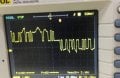
Ok so I had a breakthrough on communications networking within my robot. Originally I planned to have the main brains PC in the chest of the robot connect by USB to a "chest arduino" which would connect by single wire communication to a right arm arduino, left arm arduino, right leg arduino...
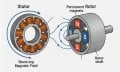
While on my journey to develop the firmware for the ESC so far I was trying to figure out how to implement all the features the original ESC has to offer in its hardware setup but then it occurred to me that I don't need most of that stuff. And a lot of the complexity that was in the original...

Ok so after further consideration I decided that the idea of adding significant modifications to a 6k lines of code 20 file assembly language behemoth firmware developed by a big company was just not prudent for me. I need to be able to go in there and add tweaks and improvements for years to...
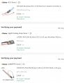
It occurred to me I might be able to find more cheap ESCs in this size profile on aliexpress and I did find some offers that were far cheaper than amazon. The ones I bought on Amazon were'n't too bad on price but these were a lot cheaper but take longer to ship from China on aliexpress. Here was...
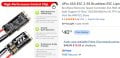
Ok so I had someone point out a very very small very very high amp ESC to me that actually would be viable from a space taken standpoint, however, it was $48 shipped which is WAY too expensive when I can make my own motor controller for $4 in parts. However, I did a search for that ESC on amazon...
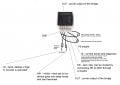
Ok I made my circuit design for my BTS7960 integrated half bridge IC chips. I plan to go with through hole passive components (resistors, capacitors) and use deadbug style so I can skip making a PCB this way. This will cut out that significant step and save time IMO. If I have trouble or...
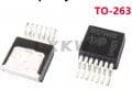
Ok so I ran the test of my PCB and try as I might the PCB was dead. Totally non-functioning. And to make matters worse, I would not have any clue of where the issue is. Could a static electric discharged have bricked the IC? Could some pad have a microscopic open circuit in its joint with the...

I couldn't find much information online about the Max9924 voltage comparator chip, so i built an small test board to experiment with the chip's modes of operations. For my project of making an igniter for a 22re, I need the chip to run in either a modified mode A1, or in mode B (perhaps mode C...
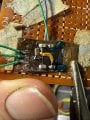
I soldered on 30ga wrapping wire for testing the PCB. The 3 on the front are 5v+ from microcontroller that tells this IC to be in "on" mode, ground from microcontroller, and PWM from microcontroller. The 2 on the back side are +8v and 0v/gnd from the batteries. This was shockingly quite hard to...
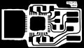
I was informed that even unused pins on the chip should have copper landing pads to solder to which will even out the forces when the whole pcb goes molten and chip is trying to auto center! It makes sense! So I added those.
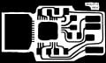
On the big output landing pad on the left, I separated the attachments to each individual pin for the chip's motor output phase rather than have the landing pad be one big blob. This encourages auto centering. Something I had not considered before until someone pointed it out. Such a simple...
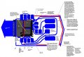
Here is a revision to my schematics where I run the trace that I had been running under the IC chip instead going around everything to avoid going under the IC chip and the problems that creates. This creative rerouting of that trace also meant I had to get clever with my other traces to...
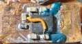
So the corner of the PCB that peeled back from the chip was a problem I decided not to tackle with a heat gun. I just don't feel too comfortable using a heat gun at this stage. Instead, I decided to remove the capacitor in the way and just hand solder the chip back on. That went smoothly...
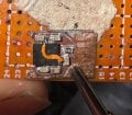
I soldered on the rest of the SMD components. I noticed the PCB peeled back off the chip in one corner though so I plan to use kapton tape to tape off everything but that corner, use a couple alligator clips to pinch the PCB onto the chip tightly so it can't move, and then use hot air from a...
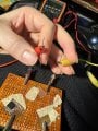
I wanted to be able to get in there and test this board for shorts and check all traces for continuity with my multimeter but felt its leads were too big for this tiny of a board setup. So I came up with this idea to use alligator jumper cables to attach sewing needles to the multimeter probes...
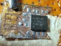
Ok so I had multiple failed attempts to solder the chip on. Despite pretinning the PCB, on both attempts when the solder went molten the chip did not center itself and lock into place as would be expected but instead slid out of position significantly both attempts. After the first attempt I...
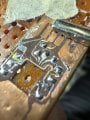
Ok I managed to apply the UV solder mask today and it seems like it worked quite smoothly. I used the tip of a small sewing needle to spread it over the trace and then held the UV light on it for 10 seconds to play it safe. I used transparent UV solder mask so you can still see the trace but its...

Ok so the Relife RL-UVH902 UV fast cure solder mask order has arrived and so has my order for a Relife UV curing light to cure the solder mask quickly and effectively. So now I just need to solder mask off that little trace that goes under the half bridge IC chip.
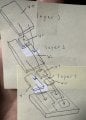
So the plan I have for the heat sinking main conductors that attach to the bottom pads of the IC chip I decided to draw up to explain it. It will be in layers. First you have the chip on the bottom facing bottom side up so the pads are exposed upwards. Then on the first attachment layer I cut...
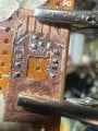
Ok I used the tip of my exacto knife to carefully scoop on low temp solder paste and then carefully drag soldered it over the key areas I wanted pre-tinned. There do not appear to be any short circuits and the amount of solder on each pad and trace seems a decent amount to me. I forgot to wipe...
