Yellow contamination on PCB. Flux? Capacitor leaked?

MisterBill2

Joined Jan 23, 2018
27,986
First: My comment about reflowing connections was for a "thru-hole" PCB. Surface mount is much different. My suggestion now is to use signal tracing. Add a test point, relative to common, to the junction of R13 and R14. That will allow learning in which segment the problem lies. Some times signal tracing is the only way to locate a fault.
 

Thread Starter

Dave Lowther

Joined Sep 8, 2016
347
My suggestion now is to use signal tracing.
Yes, that's my next step. My intention is to inject e.g. 1kHz sine wave at the RCA input (CN1) and then look with a scope on U2 pin 1 (the furthest point I've reverse engineered to). Hopefully I'll be able to make the scope trace come and go by flexing the board. If so then I can trace backwards to find the point of failure. If the circuitry up to U2 pin 1 doesn't exhibit the fault, then I'll have to do some more investigation of where the signal goes after coming out of U2 pin 1.
 

Thread Starter

Dave Lowther

Joined Sep 8, 2016
347
It's fixed and I'm very happy! Thank you so much to everyone that helped me with comments about their experience and those who offered suggestions about what I should do.
Short version:
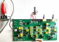
I replaced the pot RV1 (see post #34 for circuit diagram). I can now flex the board and the output signal to the speakers is perfectly stable. The pot is only connected in a temporary way in the photo. I'll fit it properly tomorrow, now that I know it's fixed the problem.
2025-03-10 15.58.55.jpg
Longer version:
I traced the signal from the input at CN1 and found that the signal was fine at RV1 pin 1 when flexing the board.
The signal at RV1 pin 2 (the wiper) came and went when I flexed the board.
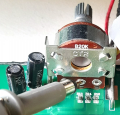
I could make the signal at RV1 pin 2 come and go just by applying mild pressure to the scope probe when it was positioned as shown below (and when it was positioned on the left or right pins of the pot):
1741624169826.png
I tried reflowing the pot's solder connections to the PCB, but that didn't fix the problem.
Removing the old pot wasn't easy, due to the metal support bracket's 2 pins, and the pot's 3 pins all being soldered to the PCB.
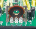
I ended up removing most of the pot by straightening those metal tags that can be seen in the above photo, and the similar tags on the front of the pot. Leaving me with what is shown in the next photo:
1741624363761.png
I'd already tried to remove most of the solder before taking the above photo. I was able to use a wide chisel tip bit to heat up 2 out of 3 pins at the same time. I applied more solder and got all 3 pins' solder to melt at the same time by sliding the bit from left to right. I pulled the wafer out with my free hand whilst the solder was liquid.
I was then able to melt the solder on the 2 metal frame solder pads, one at a time and bend it a bit to get one side out, then I got the other side out.
I don't know why that pot failed. I don't think I ever used the volume control on the back of the speaker, other than when I first bought the speakers, just to get the stereo balance correct. It's not like a regular volume control that would get used a lot and wear out the carbon track in the pot.
 
Last edited:

Tonyr1084

Joined Sep 24, 2015
9,744
It's fixed and I'm very happy! Thank you so much to everyone that helped me with comments about their experience and those who offered suggestions about what I should do.
Short version:
I replaced the pot RV1 (see post #34 for circuit diagram). I can now flex the board and the output signal to the speakers is perfectly stable. The pot is only connected in a temporary way in the photo. I'll fit it properly tomorrow, now that I know it's fixed the problem.
View attachment 344209
Longer version:
I traced the signal from the input at CN1 and found that the signal was fine at RV1 pin 1 when flexing the board.
The signal at RV1 pin 2 (the wiper) came and went when I flexed the board.
I could make the signal at RV1 pin 2 come and go just by applying mild pressure to the scope probe when it was positioned as shown below (and when it was positioned on the left or right pins of the pot):
View attachment 344210
I tried reflowing the pot's solder connections to the PCB, but that didn't fix the problem.
Removing the old pot wasn't easy, due to the metal support bracket's 2 pins, and the pot's 3 pins all being soldered to the PCB.
I ended up removing most of the pot by straightening those metal tags that can be seen in the above photo, and the similar tags on the front of the pot. Leaving me with what is shown in the next photo:
View attachment 344212
I'd already tried to remove most of the solder before taking the above photo. I was able to use a wide chisel tip bit to heat up 2 out of 3 pins at the same time. I applied more solder and got all 3 pins' solder to melt at the same time by sliding the bit from left to right. I pulled the wafer out with my free hand whilst the solder was liquid.
I was then able to melt the solder on the 2 metal frame solder pads, one at a time and bend it a bit to get one side out, then I got the other side out.
I don't know why that pot failed. I don't think I ever used the volume control on the back of the speaker, other than when I first bought the speakers, just to get the stereo balance correct. It's not like a regular volume control that would get used a lot and wear out the carbon track in the pot.
Glad you got it worked out. Those pots can sometimes be a problem. Kudos.
 

MisterBill2

Joined Jan 23, 2018
27,986
This would not be the first intermittent pot, not even the twentieth. Often it is the build-up of an insulating film on top of the resistance material. Contact cleaner can provide a temporary fix for diagnosing the problem, but only a temporary repair, usually.
 

Thread Starter

Dave Lowther

Joined Sep 8, 2016
347
This would not be the first intermittent pot, not even the twentieth. Often it is the build-up of an insulating film on top of the resistance material. Contact cleaner can provide a temporary fix for diagnosing the problem, but only a temporary repair, usually.
It wasn't the usually crackly pot sound when turning it, when working the pot worked perfectly, crackle free. If it had been the usual pot fault I'd have twigged a bit quicker
 

MisterBill2

Joined Jan 23, 2018
27,986
There is also the failure of the connection between the crimped or riveted lug and the resistive element. I am not sure what causes that, but it also happens. But not in those expensive pots with the molded base.
 

Thread Starter

Dave Lowther

Joined Sep 8, 2016
347
There is also the failure of the connection between the crimped or riveted lug and the resistive element. I am not sure what causes that, but it also happens.
When you say "expensive pots with the molded base" I assume you aren't referring to the original pot that was on the board.
The original pot doesn't look to be a better quality pot than the cheap pot I replaced it with. I happened to have a few cheap 20K pots 'in stock', so I didn't bother trying to find / order a new, better quality pot.

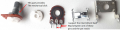
Yes, a failure between one of the the pot's solder terminals, and the pot internals, was the only cause of the problem that I could think of. This is the original pot taken apart.
1741782502411.png

What was different about the original pot, compared to the cheap pot I used to replace it, was that it had some extra parts in the pot which made some deliberate mechanical clicks when rotating. It felt a bit like a wire wound pot feels when rotatating it. Another difference was that it was clamped to the metal frame that was soldered to the board.
[Edit: Replaced the image to update which pins I suspect caused the fault. The removed image had an arrow going to the left pin. I forgot that it was the front view. On the back view, the left pin (RV1 pin 1 post #25), is the input to the pot and the middle pin is the output to the next stage]
 
Last edited:

MisterBill2

Joined Jan 23, 2018
27,986
If there is no other mechanical support for the pot when it is installed, then that soldered in mount is a good choice. Supporting a control only by it's connections is an always poor choice. Likewise for connectors.
NO, the "expensive pots with the molded base" will not be found in consumer products. They cost several dollars each, in quantity purchases. I used them in industrial equipment where failure costs were in the thousands of dollars per minute of lost production.
 

Thread Starter

Dave Lowther

Joined Sep 8, 2016
347
If there is no other mechanical support for the pot when it is installed, then that soldered in mount is a good choice. Supporting a control only by it's connections is an always poor choice.
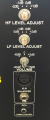
Agreed. All the controls are bolted to the back panel:
1741783386927.png
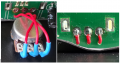
The new pot that I fitted wasn't deep enough to fit on the PCB with the metal frame, so I wired it like this:
1741783507681.png

The three holes in the PCB were already there. There are no pads / PCB tracks for those 3 holes.
 
Top