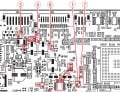
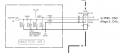
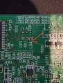
Measure the voltage at testpoint (4). Expected voltage is +3.3 V.
Measure the voltage at both sides of R252 (leading to pin-1 of CN9).
See if you can locate L204. I cannot find it.
Measure the voltage at testpoint (4). Expected voltage is +3.3 V.
Measure the voltage at both sides of R252 (leading to pin-1 of CN9).
See if you can locate L204. I cannot find it.
Are there any components on the bottom side of the board?
You can make a quick test with a piece of fine hook-up wire.
Jumper from testpoint (4) to pin-1 of CN9. For current protection, connect via a series resistor, about 100 to 1kΩ will do. What resistances do you have handy?
Keep fingers crossed that this quick test restores your sound.
Edit:
Before we go there, with your DMM set to measure resistance, measure the resistance from R252 to GND, and CN9 pin-1 to GND, always with POWER OFF.
Are there any components on the bottom side of the board?
You can make a quick test with a piece of fine hook-up wire.
Jumper from testpoint (4) to pin-1 of CN9. For current protection, connect via a series resistor, about 100 to 1kΩ will do. What resistances do you have handy?
Keep fingers crossed that this quick test restores your sound.
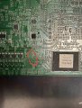
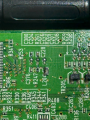
I found Point L204 on the bottom Side and there is no resistor there?
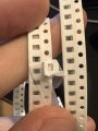
I have some SMD 0805 47R 1% and 0402 100R from an old Project, will that help?
Here the bigger ones, the others are too tiny to take a good picture with my Camera
Holy s!
Hold your horses. This doesn't make much sense.
I cannot tell from the drawings. When you flip the board, where is L204 with respect to CN9?
If there is no component installed, does it look as if the component broke away from the board?
Can you find such component laying around inside the piano?
With the DMM, check to see if there is continuity from CN9 pin-1 to either side of the L204 solder pads.
Anyway, the prognosis is looking good. No +3.3V is flowing to CN9 pin-1 if L204 is missing.
You can try putting a 100 Ω resistor where L204 is supposed to be.
But first, check if C231 is shorted. If C231 was shorting, L204 would get hot and fall off the board.
Holy s!
Hold your horses. This doesn't make much sense.
I cannot tell from the drawings. When you flip the board, where is L204 with respect to CN9?
If there is no component installed, does it look as if the component broke away from the board?
Can you find such component laying around inside the piano?
With the DMM, check to see if there is continuity from CN9 pin-1 to either side of the L204 solder pads.
Anyway, the prognosis is looking good. No +3.3V is flowing to CN9 pin-1 if L204 is missing.
You can try putting a 100 Ω resistor where L204 is supposed to be.
But first, check if C231 is shorted. If C231 was shorting, L204 would get hot and fall off the board.
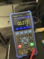
Okay so C231 gives me 0L while C227 right next to it is 0.4736 MOhm with the range set to Auto(2MOhm).
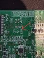
And I get continuity between CN9 pin-1 and this point:
I obviously can't find any tiny component laying inside because the piano got moved quite a bit around so no chance finding that one. But I can try to solder the 100 ohm one I have here
Check the resistance measurements again.
0L would indicate open circuit. You should be reading everything in parallel with C231, i.e. R252 + volume pot + R253 = 10kΩ
Okay I get sound now... well kinda. It's not the right sound but I guess some progress? What did I do wrong? Here again the drive folder with 2 new videos, the Sound 2 clip shows how it sounds when I play a demo.
One of the pads on L204 wont stick solder so I used a 47ohm ressistor which is bigger and soldered it directly to the point below, maybe that was the issue?
In the meantime, you can go over the previous measurements at CN9.
CN9 pin-1 should be at +3.3 V.
CN9 pin-2 should increase from 0 V to +3.3 V as you turn up the MASTER VOLUME.
Go back and look at the signals at R104 and R105 with the oscilloscope.
We are looking for signals that go between 0 V and +3.3 V to indicated that changing digital signal is being sent to the two digital-to-analog converters (DAC).
In the meantime, you can go over the previous measurements at CN9.
CN9 pin-1 should be at +3.3 V.
CN9 pin-2 should increase from 0 V to +3.3 V as you turn up the MASTER VOLUME.
Go back and look at the signals at R104 and R105 with the oscilloscope.
We are looking for signals that go between 0 V and +3.3 V to indicated that changing digital signal is being sent to the two digital-to-analog converters (DAC).
Okay so Pin-1 is 3V and pin-2 gets higher and lower between 0V and 3.3V
As for the R104 and R105 points I get this and I am pretty sure I use the scope wrong but that’s the best I could get with my newly learned knowledge: Video
Let's review what we have done and found out so far.
1) There was no +3.3D supply voltage reaching the MASTER VOLUME control potentiometer. This is fed via L204 which is missing from the circuit board (fallen off?). 47R resistor was installed instead of L204. IC101 MCU now receives proper analog volume control signal.
2) Digital audio signal now restored at R104 and R105.
We need to go back and examine the signals at the speaker power amp IC103 and the headphones DAC and HP AMP.
Confirm the voltages at /MUTE. See post #4.
With the oscilloscope, look for analog voltages at test points DAC-L and DAC-R while playing notes or demo and volume turned up.
Let's review what we have done and found out so far.
1) There was no +3.3D supply voltage reaching the MASTER VOLUME control potentiometer. This is fed via L204 which is missing from the circuit board (fallen off?). 47R resistor was installed instead of L204. IC101 MCU now receives proper analog volume control signal.
2) Digital audio signal now restored at R104 and R105.
We need to go back and examine the signals at the speaker power amp IC103 and the headphones DAC and HP AMP.
Confirm the voltages at /MUTE. See post #4.
With the oscilloscope, look for analog voltages at test points DAC-L and DAC-R while playing notes or demo and volume turned up.
When you post screen shots from the oscilloscope, tell us the VOLT/DIV and TIME/DIV settings of the oscilloscope. We cannot see the settings on the photographs and videos.
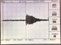
Here are two sample screen shots of middle C on a piano. The oscilloscope is set to capture once and freeze. The first photo shows a single note from start to finish lasting 300 ms. In shows the amplitude envelope of the musical note. The oscilloscope time sweep is 100 ms/div.
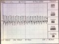
The second photo is taken with the oscilloscope set to 10 ms/div. Here you can see and measure the wave frequency.
I count 10 cycles in 38 ms or 3.8 ms per cycle. This translates to a frequency of 263 Hz which is close enough for middle C at a frequency of 262 Hz.
In both cases, the signal amplitude is about 1 division or 100 mV.
When you post screen shots from the oscilloscope, tell us the VOLT/DIV and TIME/DIV settings of the oscilloscope. We cannot see the settings on the photographs and videos.
Here are two sample screen shots of middle C on a piano. The oscilloscope is set to capture once and freeze. The first photo shows a single note from start to finish lasting 300 ms. In shows the amplitude envelope of the musical note. The oscilloscope time sweep is 100 ms/div.
The second photo is taken with the oscilloscope set to 10 ms/div. Here you can see and measure the wave frequency.
I count 10 cycles in 38 ms or 3.8 ms per cycle. This translates to a frequency of 263 Hz which is close enough for middle C at a frequency of 262 Hz.
In both cases, the signal amplitude is about 1 division or 100 mV.
Okay so something really strange happened.
I wanted to test DAC-L and R again with the explanation you gave and was preparing the board so I could test it again.
I soldered two wires on both point and on a ground point so it would be easier to test it while playing the note.
I turned the piano on and… no sound. The weird buzzing sound was gone and I thought there was no sound at all. So I was a bit upset thinking I might have damaged something and we are now back to where we started.
I desoldered the wires, cleaned the board with isopropyl alcohol and turned the piano to look if I could get the buzzing sound but no luck. Turned the volume up but still no buzzing.
And then I started a demo and suddenly it was playing! All the keys works fine too.
I don’t know why it is working and what I did to solve it but it’s working even after a few restarts. Here a video
but it’s not totally fixed. While I was playing it for a few minutes I got a really loud buzz sound for a second and it only happened once every time after I restart the piano and play for a few minutes. I tested all keys and all of them work. Not sure while a sudden buzz sound comes.
And I don’t have a clue what fixed the buzzing sound at all. Was it while soldering the wires on Dac-L and Dac-R, or did cleaning the board fixed it? Any way of finding it out? I will test it a few days before declaring it as fixed or not.
But I am really happy it is working now. Thank you so much for all of your help and time. I really really appreciate it.
Glad to hear that you got it working again. Fixing an intermittent problem is one of the most difficult problems to solve. You have to wait for it to fail in order to find the fault. As they say, "you can't fix it if it ain't broke".
You can try to trigger the fault by applying heat and cold, vibration, tapping and banging. Certainly, applying heat with a soldering iron may have been significant. We can try to narrow down the area to somewhere after the MCU, digital signals to the DACs and analog signals. It could also be caused by faulty power supply lines. Other suspects are bad solder joints, PCB traces, an intermittent component. Capacitors are more likely to fail rather than resistors.
Try to see if the fault is common to both the speakers and the headphones output. Next time it misbehaves, try plugging in the headphones and compare with the speakers.
/MUTE signal is still a prime suspect if the failure affects both speakers and headphones.
While it is still working, get a feel for what the signals look like on the oscilloscope, particularly at R104, R105, DAC-L, DAC-R.
In post #49 you had posted input voltages that were not quite +15 V. You may want to revisit this.

 Facebook
 Google
 GitHub
 Linkedin