Facebook
 Google
 GitHub
 Linkedin
Hi everyone!
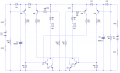
I'm currently working on an alarm system consisting of a PIR detector and a wire cut detector. I drew a circuit that seems to be working in simulator, but I would like to ask you to take a look at it. I'm concerned about missing resistors around the transistors (I don't want to fry them) but I would appreciate any other tips too. It works as follows: 1) if any of the wires are cut at the places marked by an SPST switch the buzzers should sound; 2) the 10 mF capacitor ensures that if both batteries are cut off at the same time the buzzers will sound (for a short amout of time); 3) The 555 is connected as a bistable so it remains on indefinitely. It's a bit difficult to understand at first, but as an amateur I couldn't come up with anything better (and if the burglar doesn't understand the circuit it's even better") ). The diode in the lower left is going to the PIR detector, it doesn't come into account in the wirecut part.
). The diode in the lower left is going to the PIR detector, it doesn't come into account in the wirecut part.
Thanks for your help in advance!
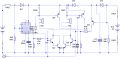
I'm currently working on an alarm system consisting of a PIR detector and a wire cut detector. I drew a circuit that seems to be working in simulator, but I would like to ask you to take a look at it. I'm concerned about missing resistors around the transistors (I don't want to fry them) but I would appreciate any other tips too. It works as follows: 1) if any of the wires are cut at the places marked by an SPST switch the buzzers should sound; 2) the 10 mF capacitor ensures that if both batteries are cut off at the same time the buzzers will sound (for a short amout of time); 3) The 555 is connected as a bistable so it remains on indefinitely. It's a bit difficult to understand at first, but as an amateur I couldn't come up with anything better (and if the burglar doesn't understand the circuit it's even better
). The diode in the lower left is going to the PIR detector, it doesn't come into account in the wirecut part.Thanks for your help in advance!
Attachments
-
 16 KB Views: 58