Facebook
 Google
 GitHub
 Linkedin
Hi,
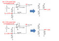
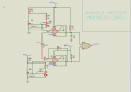
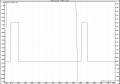
I’ve designed the window comparator shown in the images. However, when the input crosses the upper threshold, the output still gives me two pulses instead of staying at logic LOW. There are no problems between the thresholds or below the lower threshold.
Does anyone know what might be causing this or how I can fix it?
Attachments
-
 35 KB Views: 39
 -
 160.2 KB Views: 36