(Not being sarcastic here, just taking the question literally) He designs. He creates. Whether it's individual circuits or entire products or systems, analog or digital or both, he works from the specified functional and performance requirements, and the technologies available to him, to create that which is needed.
What is the difference between Applications, Systems, and Design engineers?
Application engineers assist customers in using the company's products, and/or write informational materials such as application notes and the application sections of data sheets.
"Systems Engineer" is a fancy title denoting "a guy who designs big things (most often computer-related) at a high level, overseeing the grubby, pedestrian detail work of mere plebes (i.e., the design engineers) who are lesser beings." (I'm being sarcastic here, obviously, but often that description is not too far off the mark.)
I'm retired now, and only do occasional consulting for my former place of employment. Back when I worked full-time, though, it was mainly as a combination design and applications engineer dealing with sensors and instrumentation for industrial and military application.
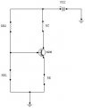
First learn how to bias the transistor into its quiescent state.
Here is a practice session:
1). choose a supply voltage (VCC)
2). choose voltage gain for the stage (Av) {NO more than 20}
3). choose quiescent collector current (IC)
Design as follows.
1). calculate the collector resistor (RC)
design for 1/2 of VCC to be applied across (RC)
so {RC = (1/2 VCC / IC)}
2). calculate the emitter swamping resistor (RE)
so {RE = (RC / Av) this will allow you to design the DC voltage gain into the amplifier.
3). Ve = (IC x RE) this is voltage at the emitter terminal.
so now you can calculate the base voltage. (VB)
{(VB = (VE + 0.7v) this is the voltage across the emitter resistor plus the base emitter inherent voltage.
4). choose a pull down resistor (RB1) in a voltage divider to be around (10 to 20 X RE.)
so (RB1 = (10 to 20 X RE)
5). (ID) is the divider current.
so ( ID = VB / RB1)
and RB2 is the supply resistor in the divider.
therefor (RB2 = ((VCC - VB) / ID)
Here are the formulas:
1). RC = (1/2 VCC / IC)
2). RE = (RC / Av)
3). VE = (IC x RE)
4). VB = (VE + Vbe)
5). RB1 = (10 to 20 X RE)
6). ID = (VB / RB1)
7). RB2 = ((VCC - VB) / ID)
After you build the circuit, then you can tweak values of any resistors to get the voltage at the collector to be around 1/2 supply votage.
Practise this using different values for VCC and IC and Av until you get familiar with how to bias the transistor into its linear region.
Once you learn this, then you will be ready to design voltage amplifying stages, with actual loads.
If I want a simple power amplifier, say to amplify an audio signal and feed it into a speaker... Do I use the speaker in place of Rc? So that the speaker becomes the load, directly connected in place of Rc, so that a lot of current passes through it? Or does it not matter ? Or should I AC couple the speaker to the transistor collector? However it seems the voltage will be small because Rc is large compared to the speakers impedance.
No. First as a simple (class A) amplifier it wastes energy vs other possible power amplifier circuits AC or DC coupled. If Rc is DC coupled that energy is also wasted in the speaker coil resistance causing it to heat, the speaker cone is displaced by the DC bias current into a position other than the natural suspension position possibly causing audio distortion from the transducer. So we want a circuit that doesn't have a large DC quiescent current but is capable of a large AC current into the speaker.
No, I can't; there are many, many considerations in making that choice, such as required voltage gain, output and input impedances, frequency response, noise level, distortion, and so forth.
Also, common-emitter transistor amplifiers (ugh!) are largely textbook stuff anymore: I haven't designed one since the advent of the operational amplifier. Life is much, MUCH better now...
Yes, it's complicated; but don't let that discourage you. The good news: experience will make it a lot LESS complicated. The bad news: usually it takes a LOT of experience to master that complexity.
As for mathematics being easier, that depends mostly on your personal aptitudes. I've never been particularly adept at mathematics, and I've always approached "working in the Equation Domain" with some degree of trepidation. Though I've certainly been able to handle maths well enough to do what I've needed to do, I do tend to think in a more intuitive fashion.
I would imagine that's because math is logically precise with few or no fuzzy or ill-defined parameters.
Learning electronic design is determining how to transform those fuzzy or ill-defined design parameters/requirements into a viable design.
Typically there's no one right answer to meet the requirements, so you try to select the best/simplest one that does the job.
Determining that is where experience comes in.
Unfortunately experience can't be readily taught and it takes time.
I would assume that it takes several years for even the best mathematicians to learn advanced mathematics.
Electronics is also a complex subject.
So don't expect to become proficient in it in a short period of time since no one does (unless perhaps they are some kind of savant).

 Facebook
 Google
 GitHub
 Linkedin